
Vehicle exhaust systems

a technology for exhaust systems and vehicles, applied in the direction of engines, mechanical equipment, machines/engines, etc., can solve the problems of heat damage, weakening and eventually breaking the muffler mounts, and holes at the point of wear and tear

Inactive Publication Date: 2009-03-31
EMLER DON R
View PDF18 Cites 24 Cited by
  • Summary
  • Abstract
  • Description
  • Claims
  • Application Information

AI Technical Summary

Benefits of technology

[0015]It is a further object and feature of the present invention to provide such a system that increases ground clearance in road-operated motorcycles.
[0025]It is a further object and feature of the present invention to provide such a system that modifies the exhaust sound emissions while reducing backpressure within the exhaust system of an internal combustion engine by maximizing the cross-sectional area and interior surface area of the system muffler core.

Problems solved by technology

Tire contact with a muffler will cause the muffler to move, thus weakening and eventually breaking the muffler mounts.
Any contact with the vehicle frame, sub-frame, or shock will eventually cause a hole to develop at the point of wear.
The side panels of most motorcycles are generally made from plastic; any contact with the muffler results in heat damage.
Restrictions in the exhaust system can prevent full evacuation of the combustion gases from the cylinder, resulting in an inability of the engine to fully recharge the cylinder with a subsequent volume of fuel / air mixture.
Unfortunately, exhaust systems often sacrifice flow in favor of other factors, for example, the reduction of sound emissions during operation.
Each method has distinct disadvantages from the standpoint of heat generation, reliability, and engine longevity.
Alternately, increasing the performance of the exhaust system may increase engine power output with relatively minor reductions in reliability.
The negative consequences of this arrangements is that low and mid RPM torque diminishes when compared to the performance characteristics of a large core, large outlet system.

Method used


Image

  • Vehicle exhaust systems
  • Vehicle exhaust systems
  • Vehicle exhaust systems

Examples


Embodiment Construction

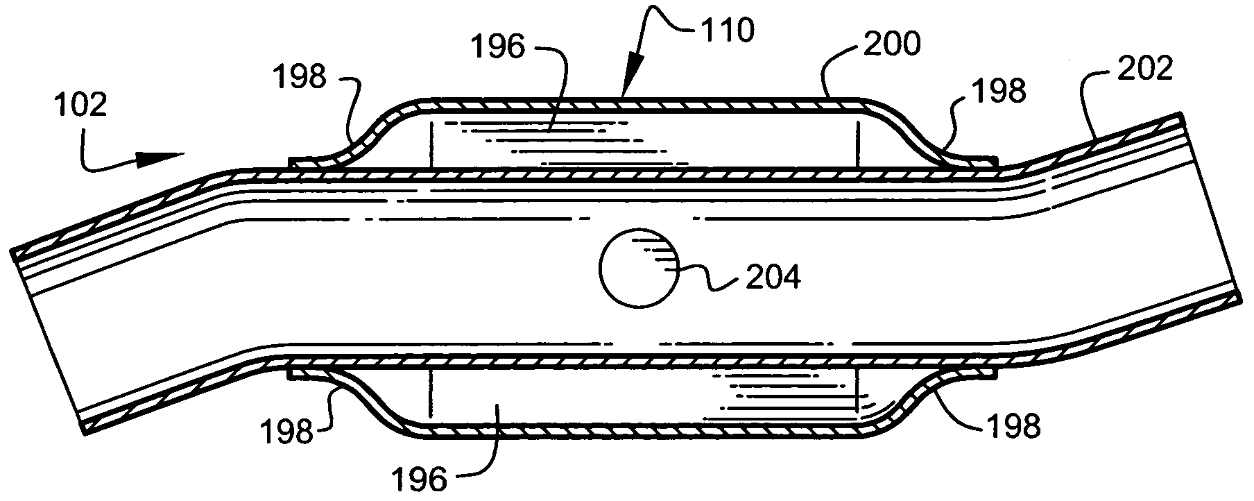
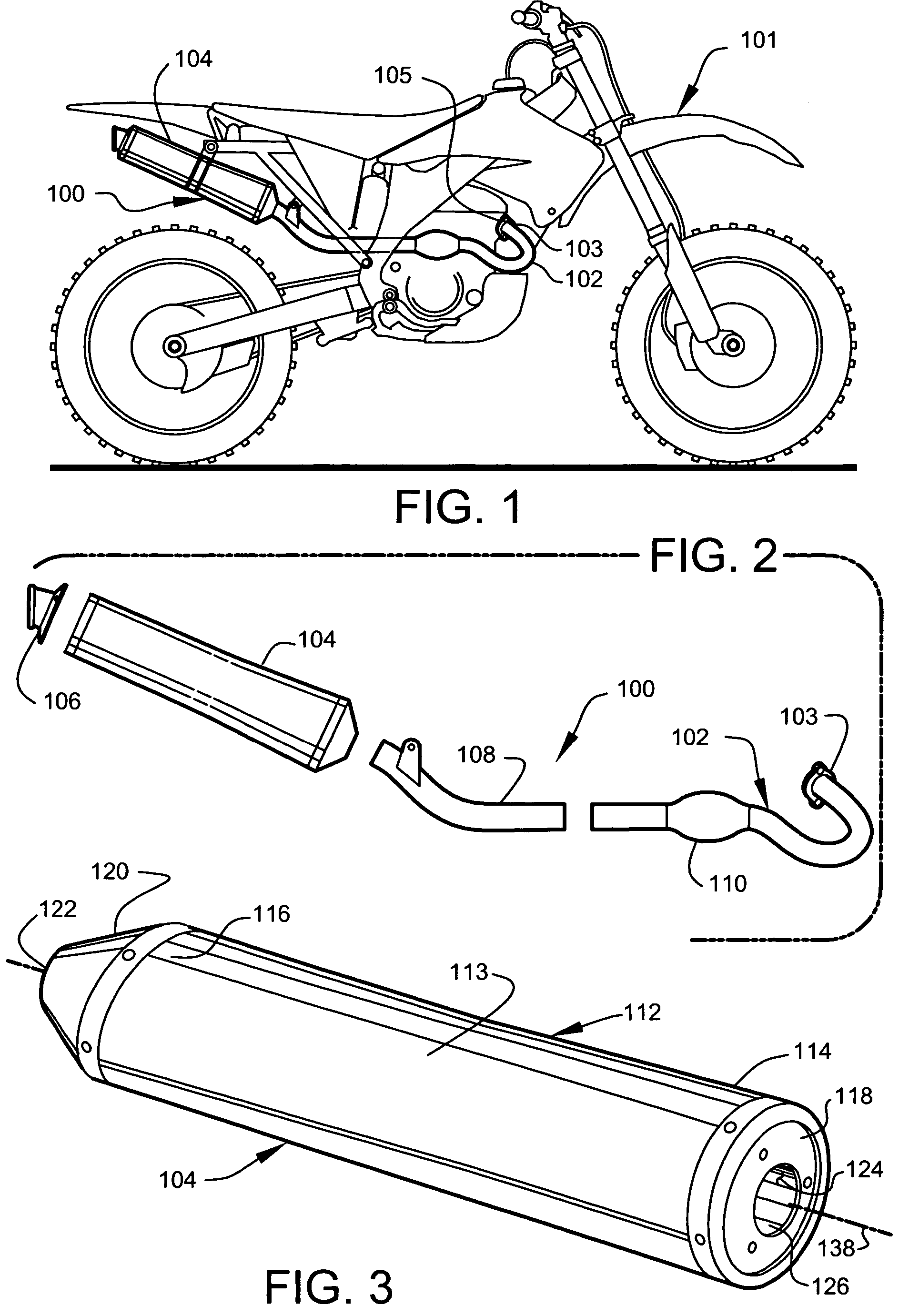
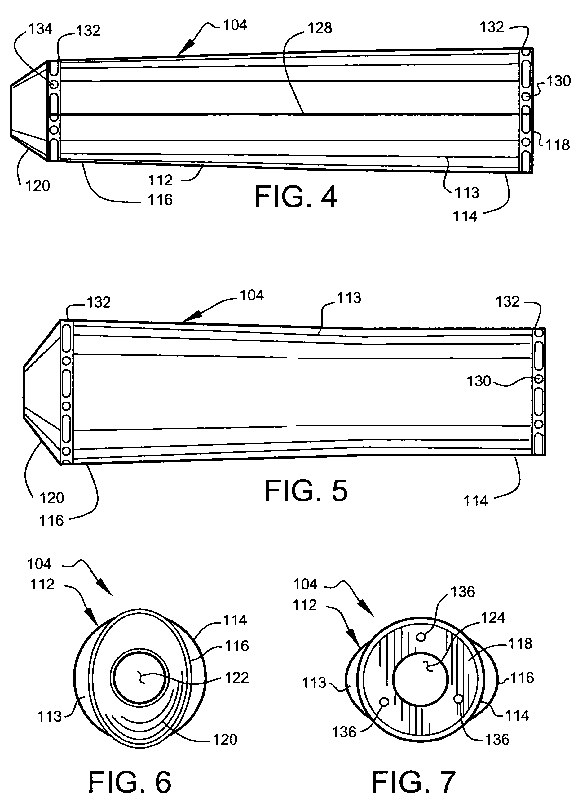
[0077]The following detailed description will be accomplished by reference to preferred embodiments and will include Applicant's current best understanding of the theory of operation of the preferred embodiments. However, Applicants do not regard themselves as bound, or their invention limited, by any particular theory of operation expressed herein, as some uncertainties exist, even in the underlying science itself.

[0078]FIG. 1 is a side view illustrating a typical vehicle application for exhaust system 100. In FIG. 1, exhaust system 100 has been incorporated into first example vehicle 101, as shown. For the purpose of the present disclosure, first example vehicle 101 comprises a four-stroke off-road motorcycle having a displacement of about 450 cc. First example vehicle 101 may preferably comprise an off-road motorcycle generally matching the specifications of model CRF 450 produced by Honda Motor Co., Inc., as shown. Those skilled in the art will appreciate that first example vehi...


PUM


Abstract

A vehicle exhaust assembly for improved evacuation of exhaust gases from an internal combustion engine. The system comprises a modular replacement exhaust system having a novel header pipe and muffler. The present invention readily adapts to a range of vehicle applications including automobiles, motorcycles, and all terrain vehicles.

Description

CROSS-REFERENCE TO RELATED APPLICATION[0001]The present application is related to and claims priority from prior provisional application Ser. No. 60 / 539,826, filed Jan. 27, 2004, entitled “VEHICLE EXHAUST SYSTEM”, and prior provisional application Ser. No. 60 / 607,445, filed Sep. 3, 2004, entitled “VEHICLE EXHAUST SYSTEM”, the contents of both of which are incorporated herein by this reference and are not admitted to be prior art with respect to the present invention by the mention in this cross-reference section.BACKGROUND[0002]This invention relates to providing a system for improved exhaust evacuation from an internal combustion engine.[0003]Internal combustion engines serve to power a majority of the powered vehicles worldwide. Typically, internal-combustion-driven vehicles comprise at least one system for transporting the exhaust gases from the combustion cylinder to at least one remote discharge point adjacent the vehicle. Commonly, the exhaust system will comprise a length of ...

Claims


Application Information

Patent Timeline
Patent Type & Authority Patents(United States)
IPC IPC(8): F01N1/02F01N1/00F01N1/04
CPCF01N1/003F01N1/006F01N1/023F01N1/04
Inventor EMLER, DON R.
Owner EMLER DON R
Learn More