
Liquid crystal television receiver for correcting optical response characteristics, LCD control method, and recording medium

a television receiver and liquid crystal technology, applied in the field of liquid crystal television receivers, can solve the problems of enlarged inter-frame data errors, inability to properly carry out overshoot drives in the aforesaid case, and inability to properly correct overshoot drives, so as to improve the conversion of input image data, improve the quality of image display, and reduce the degree of enhancing conversion

Active Publication Date: 2009-03-31
SHARP KK
View PDF22 Cites 8 Cited by
  • Summary
  • Abstract
  • Description
  • Claims
  • Application Information

AI Technical Summary

Benefits of technology

[0020]The objective of the present invention is to provide a liquid crystal television receiver that can restrain the degradation of image quality, which occurs on account of an image noise not inherent in original input image data. The image noise is produced in the following case: when input image data, whose television broadcasting standard (video format) is changed, is subjected to enhancing conversion identical with that for the image data before the change, an error in inter-frame data is enlarged.
[0044]The liquid crystal television receiver of the present invention detects a signal type of input image data by signal type detection means, i.e. detects whether the input image data is a video signal of a first broadcasting standard (video format) or a video signal of a second broadcasting standard (video format). In accordance with the result of the detection of the signal type, the liquid crystal television receiver controls and varies the degree of enhancing conversion with respect to the input image data, which is performed in the enhancing conversion means. As a result, when the input image data is the video signal of the second broadcasting standard (video format) where the frame cycle is longer than the frame cycle in the case of the first broadcasting standard, the degree of enhancing conversion is made lower than the degree of enhancing conversion when the input image data is the video signal of the first broadcasting standard (video format). With this, the enhancing conversion of the input image data can be performed in such a manner as to always cause, within a predetermined period (pixel rewriting cycle), the liquid crystal display panel to obtain a transmittance defined by the input image data, and hence high-quality image display is realized.
[0045]In this manner, the liquid crystal television receiver of the present invention can always figure out correct enhancing conversion data and supply the same to the liquid crystal display panel, in response to the input image data of different television broadcasting standards (video formats). For this reason, high-quality image display can be realized, irrespective of the type of a broadcasting standard (video format) on which the image data is based.

Problems solved by technology

For this reason, the overshoot drive cannot be properly carried out in the aforesaid case.
However, when such a multi-television receiver adopts the aforesaid conventional liquid crystal display apparatus, the overshoot drive cannot be properly done.
On this account, an error in inter-frame data is enlarged and an image noise not inherent in original input image data is produced.
As a result, the quality of displayed images deteriorates.
The image noise is produced in the following case: when input image data, whose television broadcasting standard (video format) is changed, is subjected to enhancing conversion identical with that for the image data before the change, an error in inter-frame data is enlarged.

Method used


Image

  • Liquid crystal television receiver for correcting optical response characteristics, LCD control method, and recording medium
  • Liquid crystal television receiver for correcting optical response characteristics, LCD control method, and recording medium
  • Liquid crystal television receiver for correcting optical response characteristics, LCD control method, and recording medium

Examples


embodiment 1

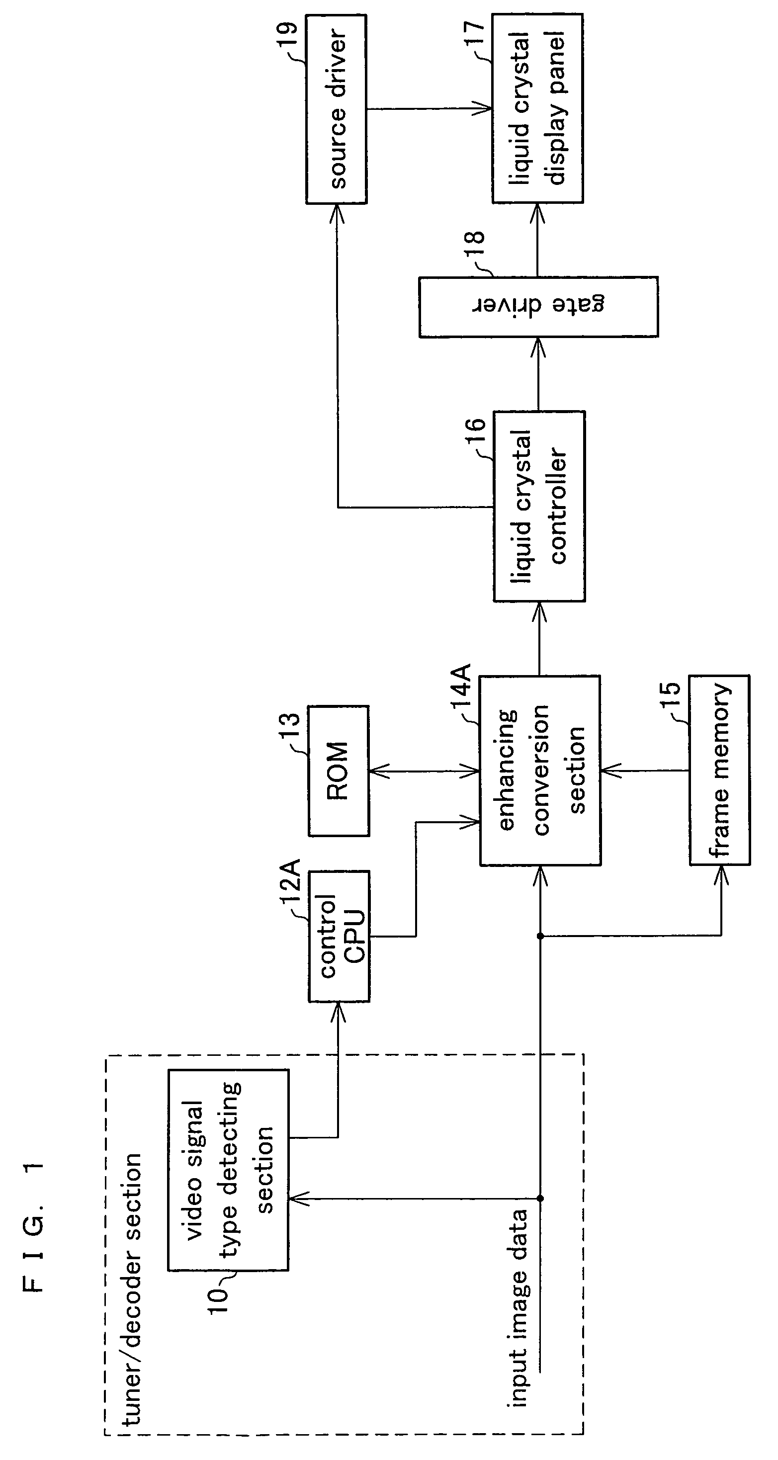
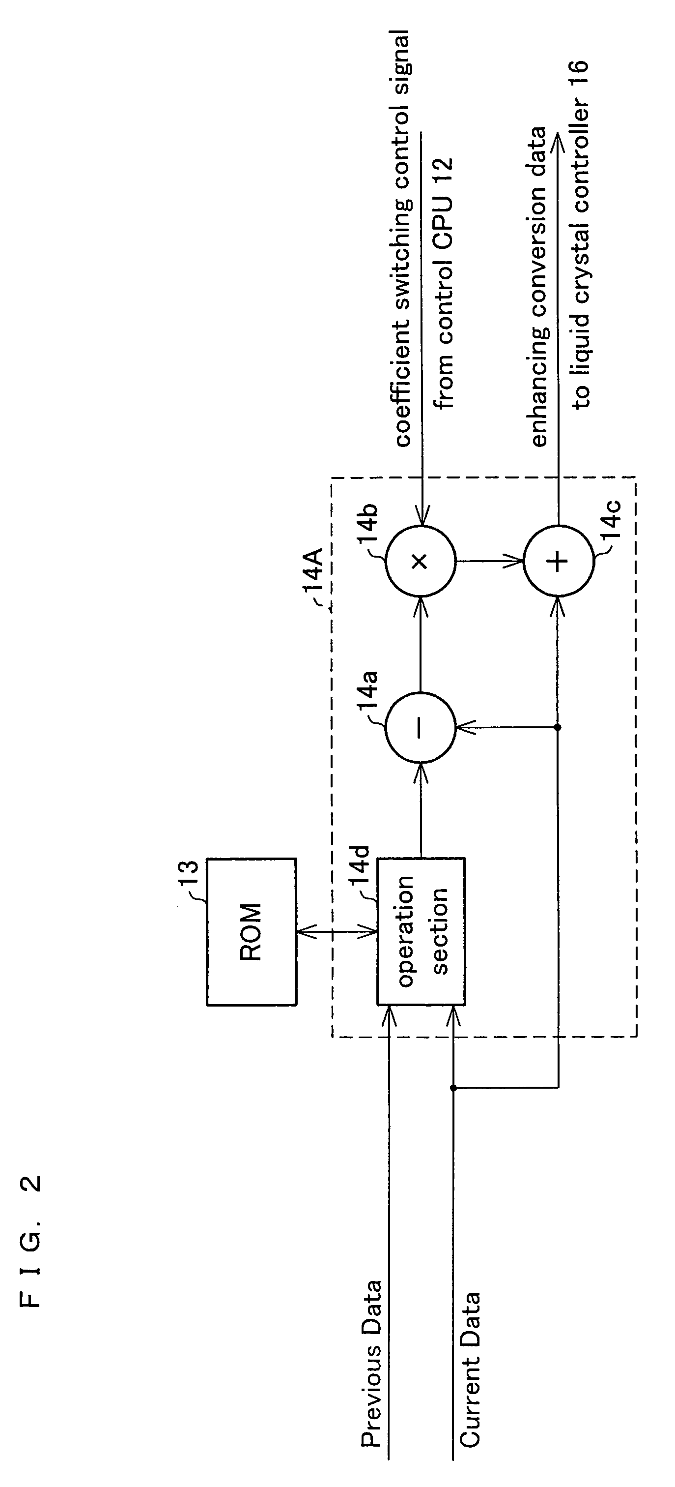
[0067]FIG. 1 illustrates Embodiment 1 of the liquid crystal display apparatus of the present invention, and FIG. 2 illustrates a case where enhancing conversion data supplied to a liquid crystal display panel is calculated from an OS parameter obtained with reference to an OS table memory (ROM) shown in FIG. 1 and a multiplication coefficient obtained in accordance with signal type data that varies according to the broadcasting standard (video format). Note that, in the figures described below, members having the same functions as those described in FIG. 15 are given the same numbers. In the following descriptions, furthermore, the enhancing conversions in enhancing conversion sections of respective Embodiments are different from each other. For this reason, in each Embodiment, the enhancing conversion section has one of the reference signs 14A through 14F. In a similar manner, control CPUs of respective Embodiments perform control in different ways, so that the control CPU in each ...

embodiment 2

[0090]FIG. 3 shows Embodiment 2, where (i) an OS table memory (ROM) storing an OS parameter for the enhancing conversion of the image data, when the input image data is a NTSC (60 Hz) video signal, and (ii) an OS table memory (ROM) storing an OS parameter for the enhancing conversion of the image data, when the input image data is a SECAM (50 Hz) video signal, are provided so as to be independent from each other. Note that, in the following description, members having the same functions as those described in FIG. 1 are given the same numbers and descriptions thereof are omitted in order to avoid overlap.

[0091]The liquid crystal display apparatus shown in FIG. 3 includes: an OS table memory (ROM) 13a that is referred to when the input image data is a NTSC (60 Hz) video signal; and an OS table memory (ROM) 13b that is referred to when the input image data is a PAL / SECAM (50 Hz) signal. In accordance with the signal type (broadcasting format) of the input image data detected by the vid...

embodiment 3

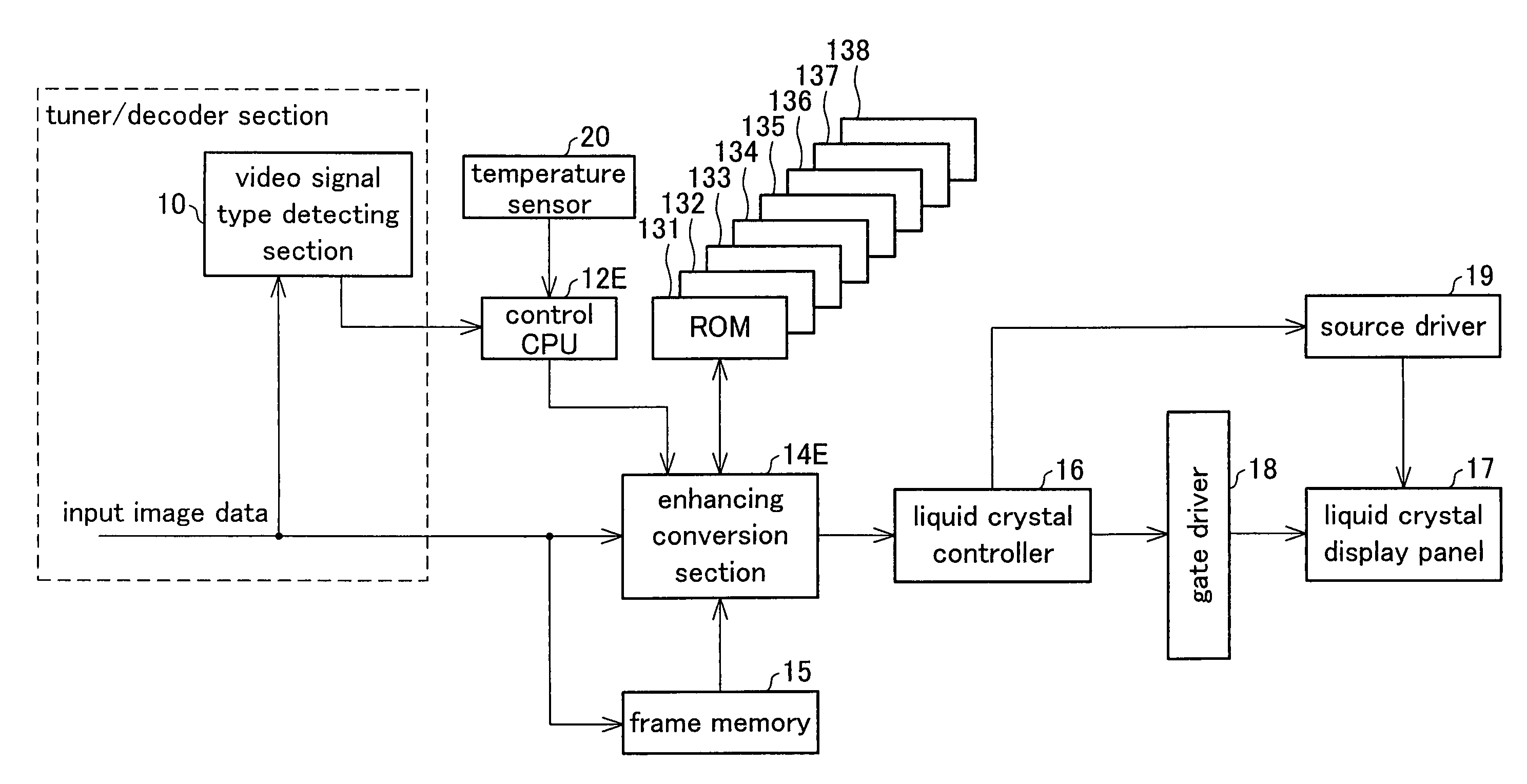
[0100]FIG. 4 illustrates Embodiment 3 where a temperature sensor is added to the arrangement of FIG. 1, and the enhancing conversion with respect to the image data is performed with reference to the OS parameter obtained in reference to the OS table memory (ROM) 13 and the multiplication coefficient corresponding to the signal type (broadcasting format) of the input image data and a temperature in the apparatus.

[0101]In the liquid crystal display apparatus shown in FIG. 4, the OS table memory (ROM) 13 stores an OS parameter (enhancing conversion parameter) optimized for a case where the input image data is a NTSC (60 Hz) video signal, and the enhancing conversion with respect to the input image data is performed using the below-mentioned multiplication coefficients α1-α4 and β1-β4 corresponding to (i) signal type detection data obtained by the video signal type detecting section 10 as the signal type detection means and (ii) temperature detection data obtained by the temperature sen...


PUM

PropertyMeasurementUnit
switching threshold temperature Th1aaaaaaaaaa
switching threshold temperature Th2aaaaaaaaaa
switching threshold temperature Th3aaaaaaaaaa

Abstract

When a video signal type detecting section detects a video signal of PAL / SECAM (50 Hz) video signal, the input image data is subjected to enhancing conversion with a degree lower than the degree of enhancing conversion in the case of NTSC (60 Hz). With this, the response speed of liquid crystal is improved and an image noise on account of excessive enhancement is eliminated, so that the deterioration in image quality is prevented. As a result, the enhancing conversion with respect to the input image data is performed in such a manner as to compensate the optical characteristics of the liquid crystal display panel, and an image noise on account of excessive enhancing conversion with respect to PAL / SECAM (50 Hz) image data, and hence high-quality image display is realized.

Description

TECHNICAL FIELD[0001]The present invention relates to a liquid crystal television receiver that reproduces images using a liquid crystal display panel, and particularly relates to a liquid crystal television receiver that can improve optical response characteristics of the liquid crystal display panel.BACKGROUND ART[0002]In these years, light and thin displays have been in high demand because light and thin personal computers and television receivers have appeared. In response to the demand, flat-panel displays such as liquid crystal displays (LCD) have been developed for replacing cathode ray tubes (CRT).[0003]An LCD is a display in which an electric field is applied to an anisotropic dielectric liquid crystal layer between two substrates, and a desired video signal is obtained by controlling an amount of light passing through the substrates by adjusting the intensity of the electric field. Such an LCD is typically adopted as a simple flat-panel display for a mobile device. In part...

Claims


Application Information

Patent Timeline
Patent Type & Authority Patents(United States)
IPC IPC(8): H04N13/00G09G3/36G02F1/133G09G3/20H04N5/46H04N5/66
CPCG09G3/3648G09G2320/0252G09G2340/16G09G2320/041G09G2320/0257G09G3/36G02F1/133G09G3/20H04N5/46
Inventor FUJINE, TOSHIYUKIOSADA, TOSHIHIKOKIKUCHI, YUJIYOSHII, TAKASHI
Owner SHARP KK
Learn More