
Filtering assembly and a feedthrough assembly

a filtering assembly and assembly technology, applied in the field of filtering assembly for feedthrough, can solve the problems of inability to get reliable leakage testing results, high manufacturing cost, and state of the art feedthrough assembly can not be easily minimized, so as to avoid leakage/creepage currents

Inactive Publication Date: 2009-03-31
BIOTRONIK SE & CO KG
View PDF9 Cites 12 Cited by
  • Summary
  • Abstract
  • Description
  • Claims
  • Application Information

AI Technical Summary

Benefits of technology

[0021]In a further preferred embodiment the filtering assembly comprises at least one capacitive element which is formed by a ceramic capacitor. Ceramic capacitors are very reliable in operation and have a low thermal coefficient.
[0024]The inventive feedthrough assembly has excellent EMI filtering properties and is easy to manufacture at low cost.
[0030]The inventive multi-leaded feedthrough assembly is capable of reliably filtering EMI at the point of entry of the signals into the implantable medical device. The assembly can be manufactured easily and inexpensively, tested with reliable results and allows for integration of further electrical components.
[0034]Additionally the first conductive layer is accommodated at the side of the second insulating substrate that is not directed to the inner section of the header but at the side of the second insulating substrate that is directed to the opposite direction. Thereby any mechanical contact between the first conductive layer and the header can be avoided leading to a longer working life of the filtering assembly.
[0036]In another embodiment there is a clearance between the end face of the inner section of the header opposite to the second insulating substrate and the second insulating substrate. This clearance can be advantageous especially with regard to defibrillators because leakage / creepage currents are avoided.

Problems solved by technology

The above mentioned state of the art feedthrough assemblies for EMI filtering have the disadvantage, that on the one hand they are expensive in manufacturing and on the other hand it is impossible to get reliable results in leakage testing because of their complicated structure.
Additionally, the state of the art feedthrough assemblies can not easily be minimized.
However, the direct connection or bonding of the discoidal capacitive device to the supportive surface of the header may cause difficulties in the manufacturing procedure and result in less reliability during its operation because the header and the discoidal capacitive device have different thermal expansion coefficient.

Method used


Image

  • Filtering assembly and a feedthrough assembly
  • Filtering assembly and a feedthrough assembly
  • Filtering assembly and a feedthrough assembly

Examples


Embodiment Construction

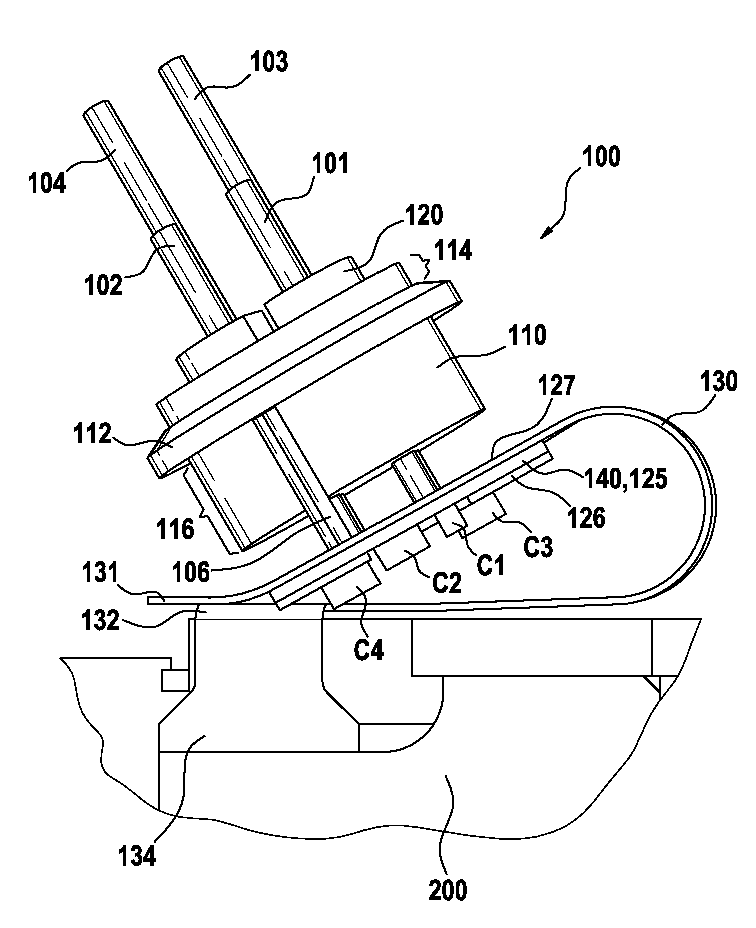
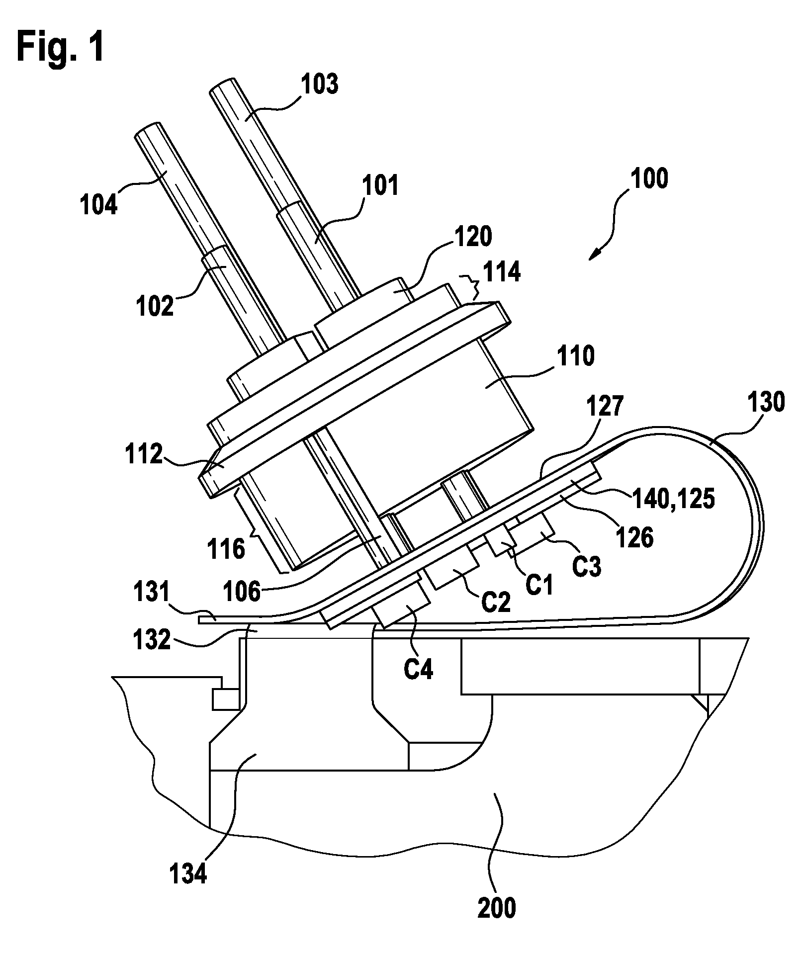
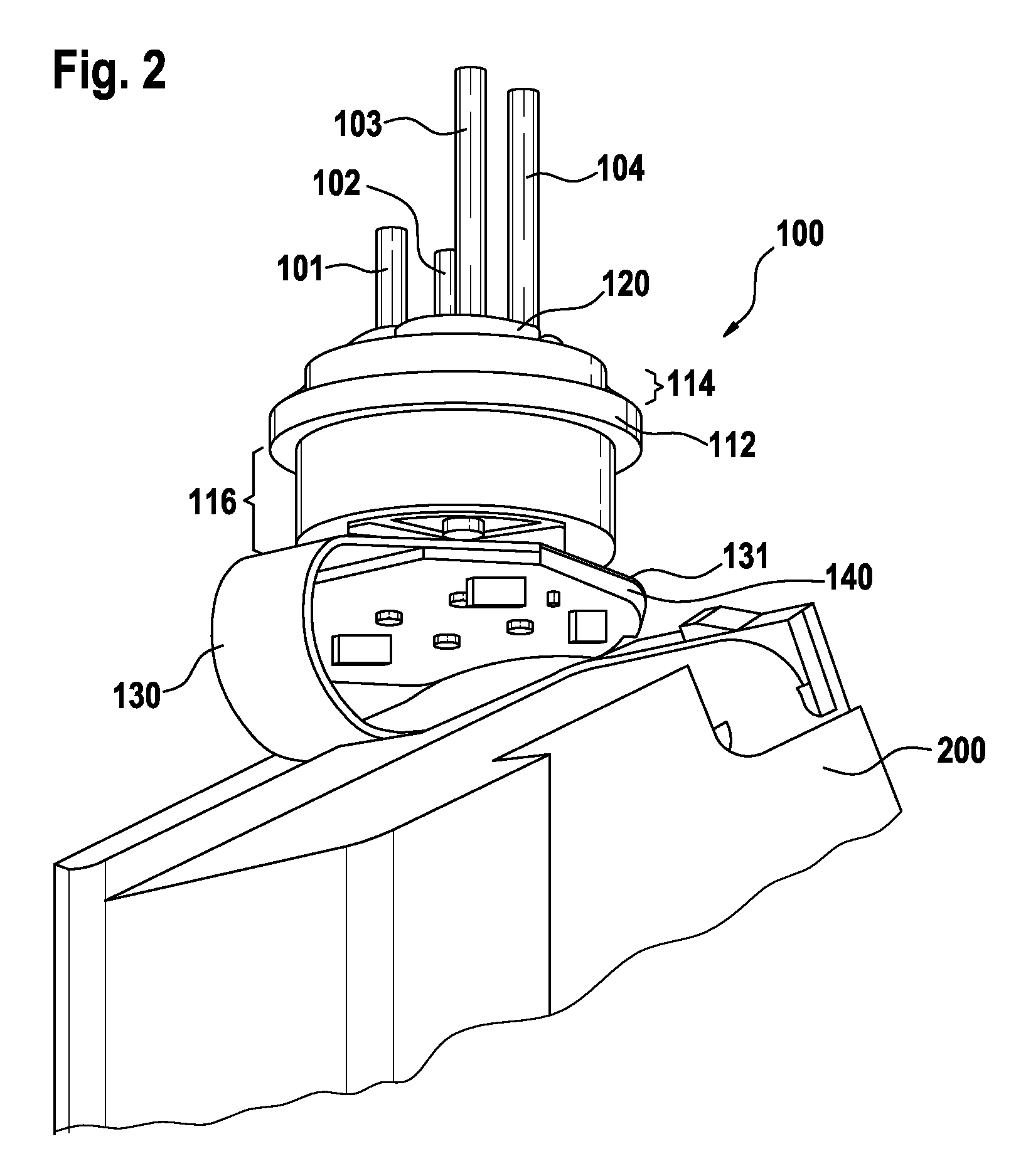
[0046]FIG. 1 depicts a preferred embodiment of an inventive feedthrough assembly 100 which is connected to an interior element 200 of an implantable medical device, such as a cardiac pacemaker. The interior element 200 may transfer or process the electrical signals which are connected through the housing or case (not shown) of the medical device.

[0047]The feedthrough assembly 100 comprises four cylindrically conducting pins 101, 102, 103 and 104 (operating pins). The pins 101 and 102 protrude with shorter ends from the upper side (in FIG. 1) of a header 110 compared to the length of the protruding ends of pins 103 and 104, respectively. These ends of pins 101 to 104 are referred to as first ends. The assembly 100 further comprises a cylindrically ground pin 106. The pins 101 to 104 and 106 are preferably made of a metal.

[0048]The operating pins 101 to 104 and ground pin 106 are disposed within respective openings in the cylindrically formed header 110, wherein the pins 101 to 104 fu...


PUM


Abstract

Filtering assembly for a feedthrough, for implantable medical devices, having operating conductive pin(s) and a ground conductive pin. The filtering assembly has:first insulating substrate,first conductive layer accommodated at first side of first insulating substrate and second conductive layer accommodated at second side of first insulating substrate opposing first side,first conductive layer comprises a conductive ground ring accommodated that surrounds the circumference of one end of the operating conductive pins and capacitive element(s), wherein each of the capacitive element(s) provides on the first side a connection to the operating conductive pin(s) and on the second side a connection to the ground ring, wherein the ground ring is connected to the ground pin,the second conductive layer comprises a ground plane providing connection to the ground ring of the first conductive layer and a connection to the ground pin.Further directed to a feedthrough assembly comprising the inventive filtering assembly.

Description

[0001]This application claims the benefit of U.S. Patent Application 60 / 909,722, filed 3 Apr. 2007, the specification of which is hereby incorporated herein by reference.BACKGROUND OF THE INVENTION[0002]1. Field of the Invention[0003]The present invention relates to a filtering assembly for a feedthrough, preferably for implantable medical devices, wherein said feedthrough comprises at least one operating conductive pin and a ground conductive pin and a respective feedthrough assembly.[0004]2. Description of the Related Art[0005]Feedthrough assemblies are generally well-known in the art for connecting electrical signals through the housing or case of an electronic instrument, for example of an active implantable medical device, such as a cardiac pacemaker, an implantable hearing device, a defibrillator, a neurostimulator, a drug pump or the like.[0006]A known feedthrough assembly comprising a multitude of electrically conductive pins is disposed within a respective one of a multitud...

Claims


Application Information

Patent Timeline
Patent Type & Authority Patents(United States)
IPC IPC(8): H01G4/35
CPCA61N1/3754
Inventor ELAM, RALPHATKIN, PHILIP J.AYTON, MICHAEL J.LECOMPTE, MARION RONALDDIGBY, DENNISHOMAYOUN, HABIB
Owner BIOTRONIK SE & CO KG
Learn More