System and method for providing switching to power regulators

a technology of power regulator and power supply, applied in the field of integrated circuits, can solve the problems of wasting large amount of energy, generating excessive heat for portable devices, and insufficient power efficiency of portable electronics, and achieves the effects of reducing the power consumption of switching devices and unwanted emi, reducing the power consumption of unwanted emi, and adjusting the response tim

Active Publication Date: 2009-03-31
ON BRIGHT ELECTRONICS SHANGHAI
View PDF5 Cites 82 Cited by
  • Summary
  • Abstract
  • Description
  • Claims
  • Application Information

AI Technical Summary

Benefits of technology

[0016]It is to be appreciated the present invention provide various advantages. According to various embodiments, the present invention provides a solution for reducing power consumption of switching devices and unwanted EMI. More particularly, the present invention offers a higher degree of flexibility in the design and implementation of power system. According to various embodiments, the present invention provides the ability to adjust the response time and efficient of power switch. For example, the present invention can be easily implemented with integrated switch mode power converter design. According to an embodiment, the present invention can also be practiced in a switch mode power converter design where power controller and power switch are implemented on separate chips. There are other benefits as well.

Problems solved by technology

While linear regulators have been used for many years, their power efficiency is often inadequate for portable electronics.
For example, due to low power efficiency, linear regulators often waste large amount of energy and generate excessive heat for portable devices.
However, for various applications, the conventional switch mode converter is often inadequate.
For example, switching regulators are typically more complex and more expensive, their switching currents can cause noise problems if not carefully suppressed, and simple designs may have a poor power factor.

Method used


Image

  • System and method for providing switching to power regulators
  • System and method for providing switching to power regulators
  • System and method for providing switching to power regulators

Examples


Embodiment Construction

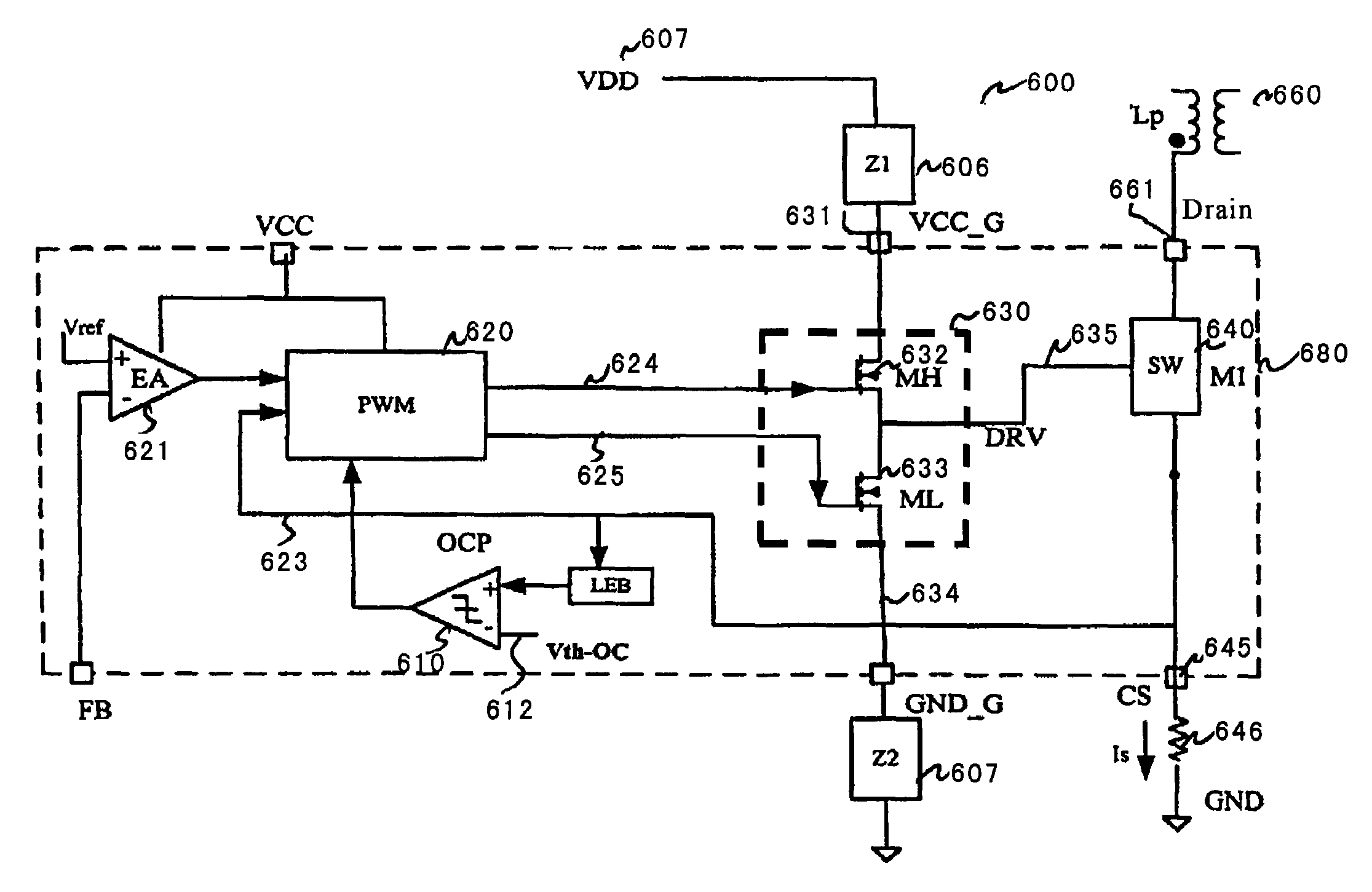
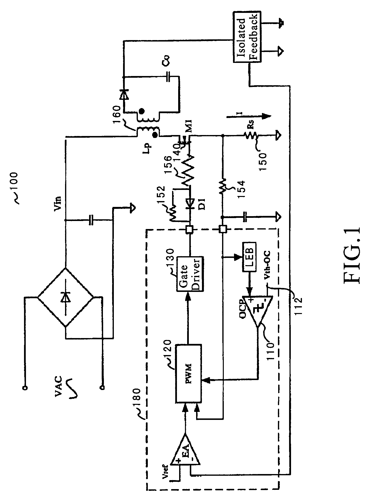
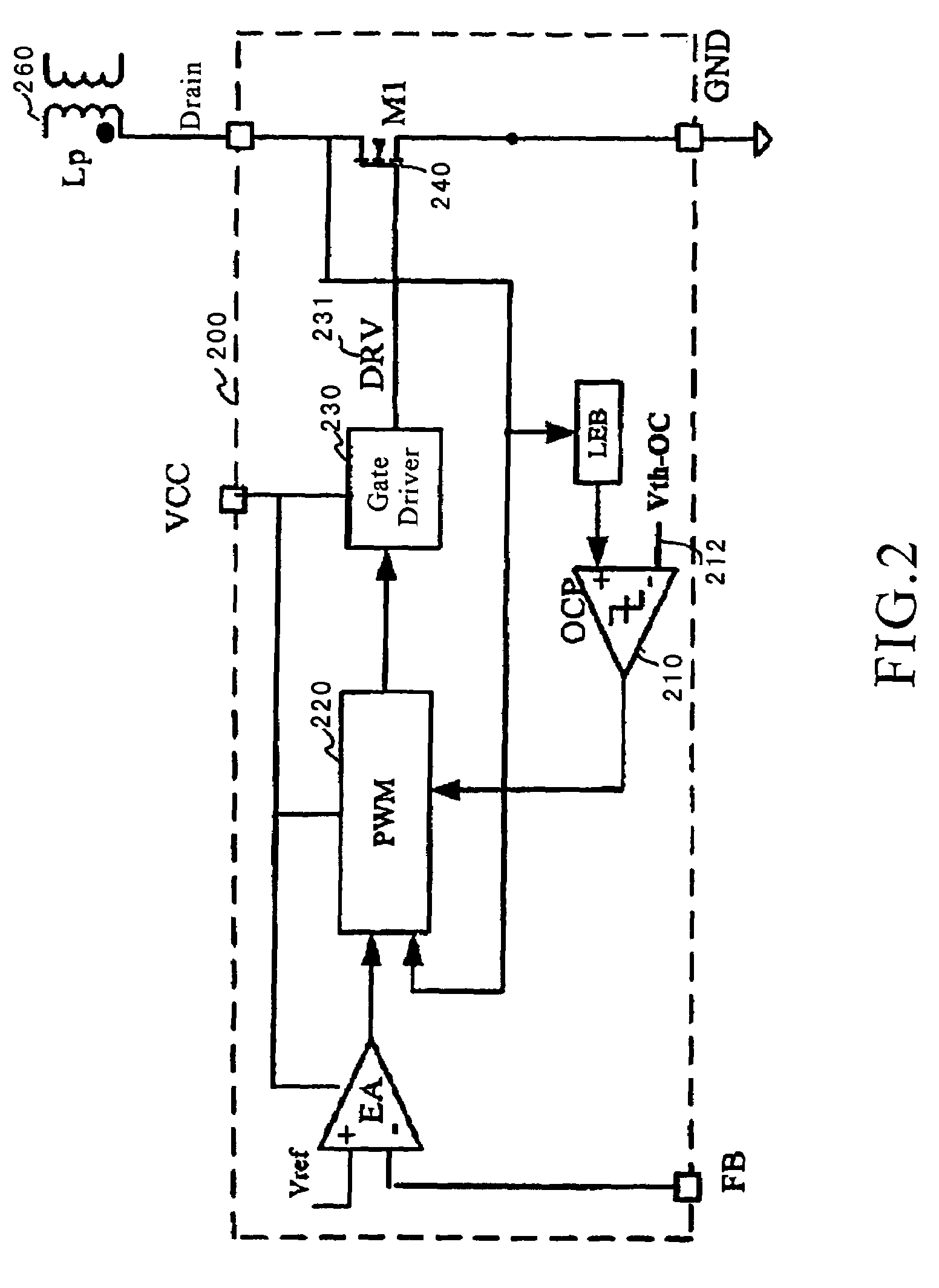
[0029]The present invention is related to integrated circuits. More specifically, the present invention can be applied to controllers used for switch mode power supply. According to various embodiments, the present invention provides integrated power switch implemented with different types of transistors. Merely by way of example, the present invention can be used in switch mode power conversion system including, among other things, offline fly-back converters and forward converters. But it would be recognized that the invention has a much broader range of applicability.

[0030]As explained above, conventional switch mode converter is often inadequate. For example, switching regulators are typically more complex and more expensive, their switching currents can cause noise problems if not carefully suppressed, and simple designs may have a poor power factor.

[0031]Over the years, with development in integrated circuits, various attempts have been made to integrate power switch and the P...


PUM


Abstract

System and method for providing switching to power regulators. According to an embodiment, the present invention provides system for providing switching. The system includes a first voltage supply that is configured to provide a first voltage. The system also includes a second voltage supply that is configured to provide a second voltage. The second voltage being independent from the first voltage. The system additionally includes a controller component that is electrically coupled to the first voltage supply. For example, the controller component being configured to receive at least a first input signal and to provide at least a first output signal. Additionally, the system includes a gate driver component that is electrically coupled to the second voltage supply. The gate driver component is configured to receive at least the first output signal and generated a second output signal in response to at least the second voltage and the first output signal.

Description

CROSS-REFERENCES TO RELATED APPLICATIONS[0001]This application claims priority to Chinese Patent Application No. 200610027041.5, filed May 24, 2006, titled “System and Method for Providing Switching to Power Regulators,” by inventors Zhiliang Chen, Shifeng Zhao, Lieyi Fang, and Zhenhua Li, commonly assigned, incorporated by reference herein for all purposes.BACKGROUND OF THE INVENTION[0002]The present invention is related to integrated circuits. More specifically, the present invention can be applied to controllers used for switch mode power supply. According to various embodiments, the present invention provides integrated power switch implemented with different types of transistors. Merely by way of example, the present invention can be used in switch mode power conversion system including, among other things, offline fly-back converters and forward converters. But it would be recognized that the invention has a much broader range of applicability.[0003]Power converters are widely...

Claims


Application Information

Patent Timeline
Patent Type & Authority Patents(United States)
IPC IPC(8): H02M3/335
CPCH02M3/33523H02M2001/0006H02M1/0006
Inventor CHEN, ZHILIANGZHAO, SHIFENGFANG, LIEYILI, ZHENHUA
Owner ON BRIGHT ELECTRONICS SHANGHAI
Why Eureka
Try Eureka