Superconducting magnet configuration with reduced heat input in the low temperature regions

a superconducting magnet and low temperature technology, applied in the direction of superconducting magnets/coils, geological measurements, using reradiation, etc., can solve the problems of large electric heating power, only a highly reduced and substantially insignificant heating power, etc., to achieve small mechanical oscillations, large electrical conductivity, and easy adjustment

Active Publication Date: 2009-04-07
BRUKER BIOSPIN
View PDF10 Cites 23 Cited by
  • Summary
  • Abstract
  • Description
  • Claims
  • Application Information

AI Technical Summary

Benefits of technology

[0027]In accordance with the invention, all low temperature oscillation systems have a considerably higher electrical conductivity value than the at least one warm oscillation system, and therefore the major part of the electric heating power is produced in the at least one warm oscillation system, at which location, the emitted heat neither endangers the superconducting wire nor burdens an associated helium-based cooling system. Cooling is also considerably facilitated and less expensive compared to the low temperature oscillation systems. The following preferably applies for the at least one warm oscillation system (R2, R2′):
[0050]In another preferred embodiment, 1.5*q1<q2 and preferably 2*q1<q2. The characteristic mechanical value of the at least one low temperature oscillation system can be easily adjusted through suitable material selection, e.g. copper. The resonance frequencies of the low temperature and warm oscillation sections differ greatly and the oscillation coupling is reduced.

Problems solved by technology

Due to the high electrical conductivity values p1 of all low temperature oscillation systems, the latter generate only a highly reduced and substantially insignificant heating power.
These oppositely phased oscillations cause very large electric heating power in the at least one warm oscillation system which are highly damped in all warm and low temperature oscillation systems.

Method used


Image

  • Superconducting magnet configuration with reduced heat input in the low temperature regions
  • Superconducting magnet configuration with reduced heat input in the low temperature regions
  • Superconducting magnet configuration with reduced heat input in the low temperature regions

Examples


Embodiment Construction

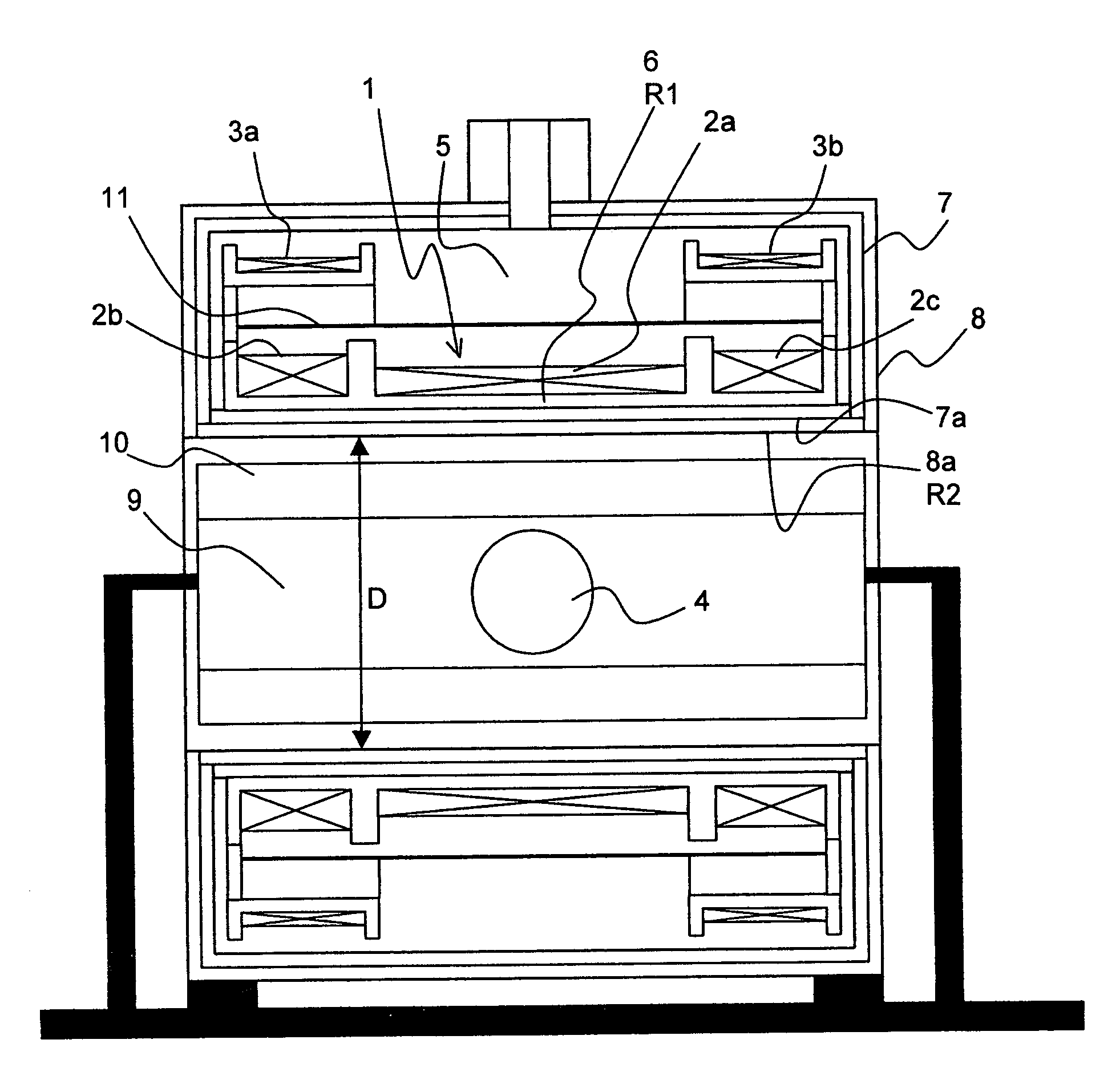
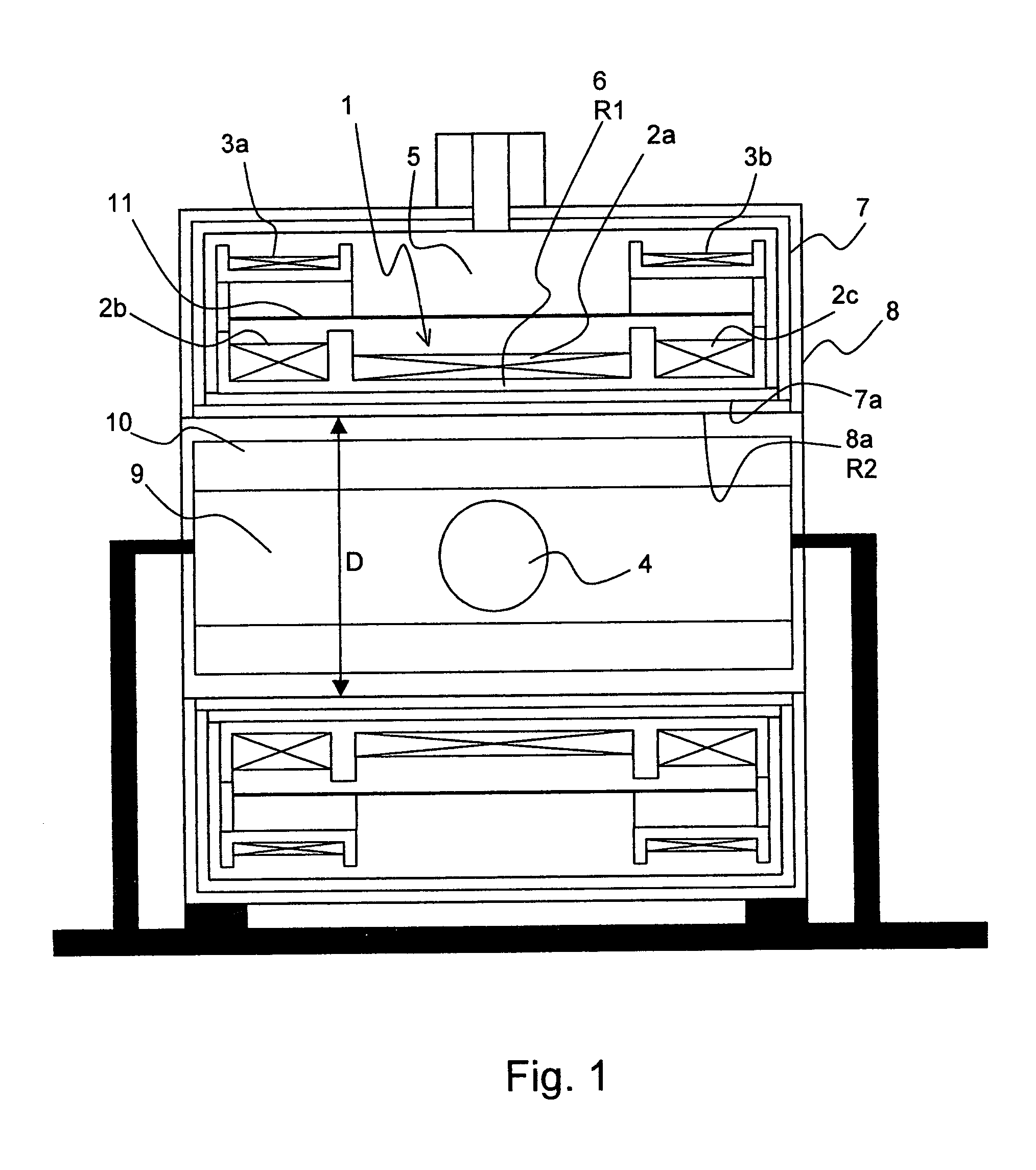
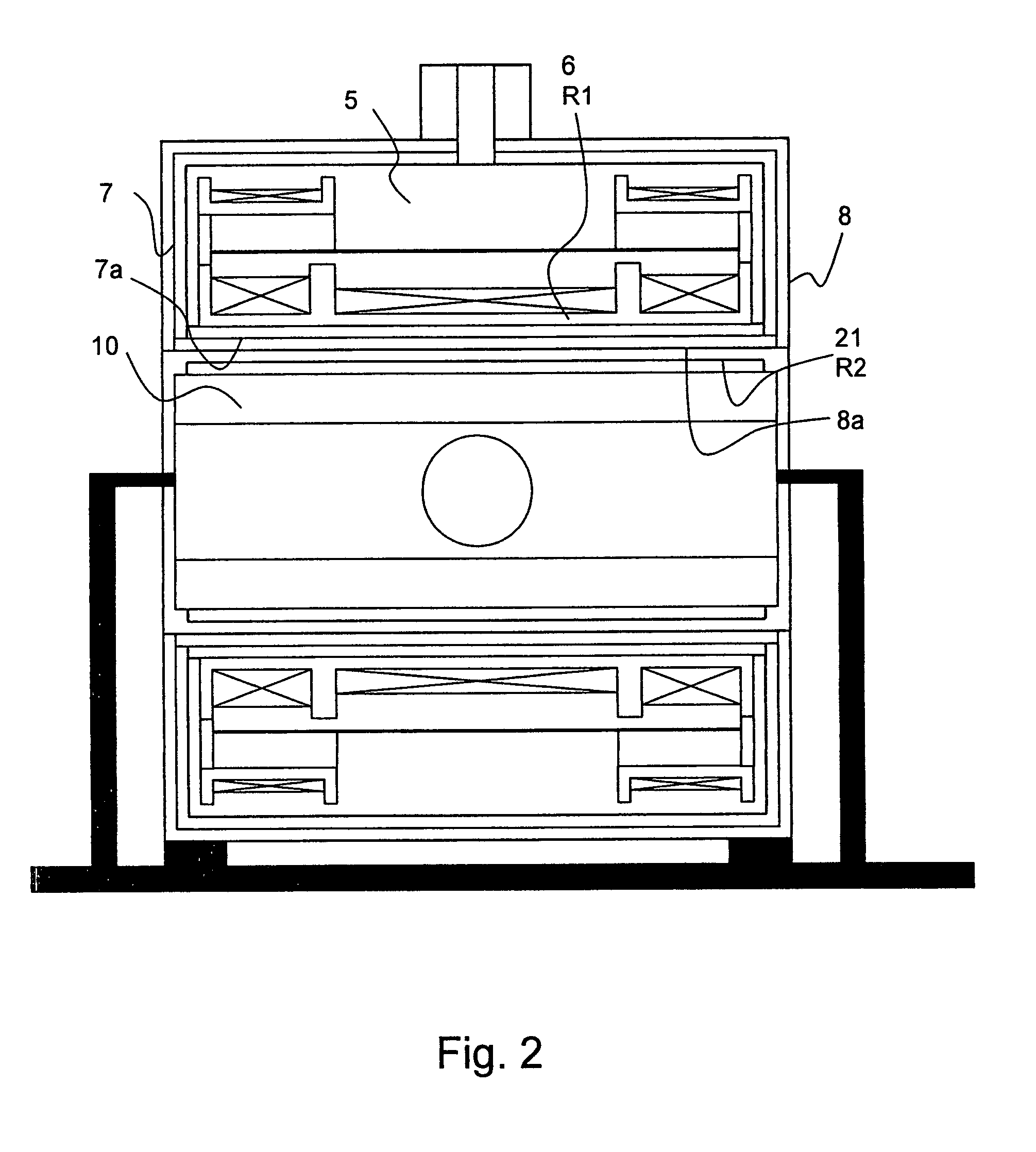
[0068]The invention concerns the improvement of a superconducting magnet configuration of a magnetic resonance apparatus.

[0069]Superconducting magnet configurations which can be improved by the present invention are disclosed e.g. in DE 10127822 A1 and U.S. Pat. No. 6,707,302 B2.

[0070]The magnet configuration comprises a magnet winding of superconducting wire which is disposed about a radially inner carrier tube R1. The carrier tube and the magnet winding form the superconducting magnet coil, optionally together with magnet windings of superconducting wire which are disposed radially further outside and e.g. reduce the stray magnetic field in the surroundings of the magnet configuration. Materials for the carrier tubes R1 are generally aluminium alloys or nonmagnetic stainless steel. The magnet coil is at an operating temperature of less than 10 K so that the superconducting wire is in a superconducting state. The magnet coil is located in a cryostat in order to provide this operati...


PUM


Abstract

The invention concerns a magnet configuration comprising a superconducting magnet coil (1) within which a gradient system is to be switched. All low temperature oscillation systems (R1) with a temperature T1<10K within the magnet coil (1) are produced from a material having good electrical conducting properties, and at least one warm oscillation system (R2) with a temperature T2>10K within the magnet coil (1) has worse electrical conducting properties and has a considerably different mechanical resonance frequency (separation approximately 500 Hz or more) than at least one of the low temperature oscillation systems (R1). This reduces the undesired heating power supplied to the low temperature oscillation systems due to mechanical oscillations and induced eddy currents.

Description

[0001]This application claims Paris Convention priority of DE 10 2006 018 650.8 filed Apr. 21, 2006 the complete disclosure of which is hereby incorporated by reference.BACKGROUND OF THE INVENTION[0002]The invention concerns a superconducting magnet configuration for a magnetic resonance apparatus, comprising:[0003]a substantially cylindrical magnet coil with a magnet winding of superconducting wire for generating a magnetic field B in a working volume;[0004]a room temperature bore which is coaxial to the magnet coil and contains the working volume; and[0005]several electrically conducting oscillation systems (R1, R2, R2′) which are disposed radially inside the magnet winding of the magnet coil, wherein each oscillation system (R1, R2, R2′) has a uniform oscillation behavior and can oscillate relative to any other oscillation system, wherein each oscillation system (R1, R2, R2′) is substantially tubular and disposed coaxially to the room temperature bore, wherein each oscillation sy...

Claims


Application Information

Patent Timeline
Patent Type & Authority Patents(United States)
IPC IPC(8): G01V3/00
CPCG01R33/3804G01R33/3806G01R33/3815H01F6/04G01R33/4215
Inventor WESTPHAL, MICHAEL
Owner BRUKER BIOSPIN
Why Eureka
Try Eureka