Method for x-ray image recording of a non-centric imaging area using an x-ray imaging system, and x-ray imaging system

a technology of x-ray imaging and non-centric imaging, applied in the field of x-ray image recording of a non-centric imaging area using an x-ray imaging system, and x-ray imaging system, can solve problems such as inability to be used in many directions

Active Publication Date: 2009-04-07
SIEMENS HEALTHCARE GMBH
View PDF3 Cites 11 Cited by
  • Summary
  • Abstract
  • Description
  • Claims
  • Application Information

AI Technical Summary

Benefits of technology

[0006]An object of the present invention consists in setting down a method and an X-ray imaging system for carrying out the method, which also allow three-dimensional imaging of areas of an object which cannot be brought centrically into the circular path described by the focus of the X-ray source in the case of conventional C-arm systems.
[0011]With the present method, even in the case of smaller areas of interest which are not situated centrically within the circular path of the X-ray focus a dose reduction is achieved for the patient when the X-ray beam is collimated accordingly to the smaller area. Through this collimation, the angle of beam spread of the X-ray source is restricted with the aid of diaphragms and the imaging area is thereby made smaller and the patient dose reduced.
[0013]This procedure can also be utilized in order to enlarge the overall imaging area. To this end, a plurality of overlapping imaging areas are chosen and recorded in successive scans, whereby the projections of the individual scans are then merged again in a virtual projection prior to the reconstruction. Here too, with regard to this virtual projection, the image data from X-ray images from the different scans, which have been recorded with the X-ray focus at the same position, are merged. In this manner, during the later image reconstruction using the merged image data, artifacts resulting from truncated projection images can be avoided.

Problems solved by technology

However, if other areas are to be represented, then problems result on account of the above condition.
It is thus not possible in many practical situations, for example with regard to vertebroplasty or kyphoplasty, to carry out the rotation of the C-arm on a circular path around the desired imaging area since collisions would occur in this case between the C-arm and the patient, the patient support or instruments in use.

Method used


Image

  • Method for x-ray image recording of a non-centric imaging area using an x-ray imaging system, and x-ray imaging system
  • Method for x-ray image recording of a non-centric imaging area using an x-ray imaging system, and x-ray imaging system
  • Method for x-ray image recording of a non-centric imaging area using an x-ray imaging system, and x-ray imaging system

Examples


Embodiment Construction

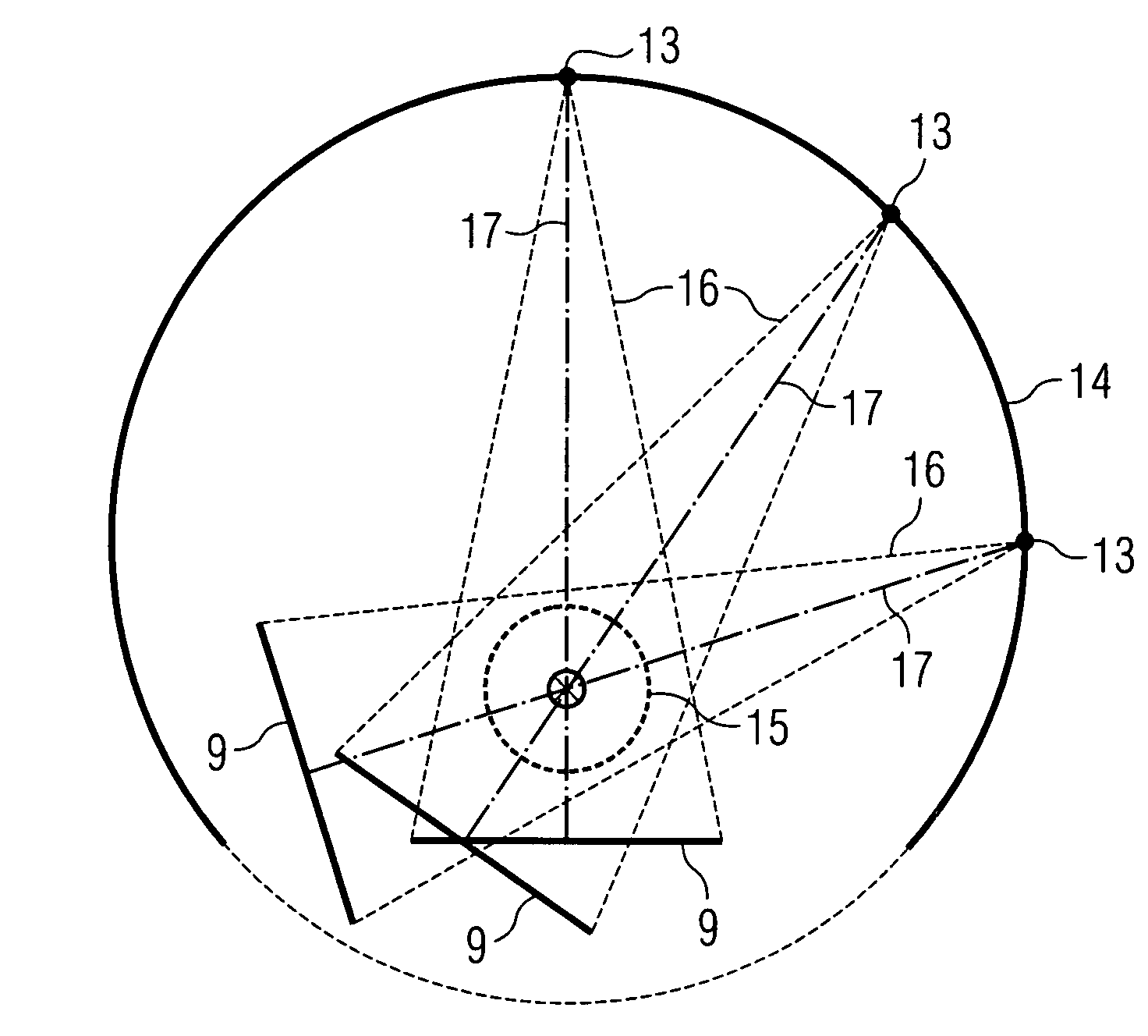
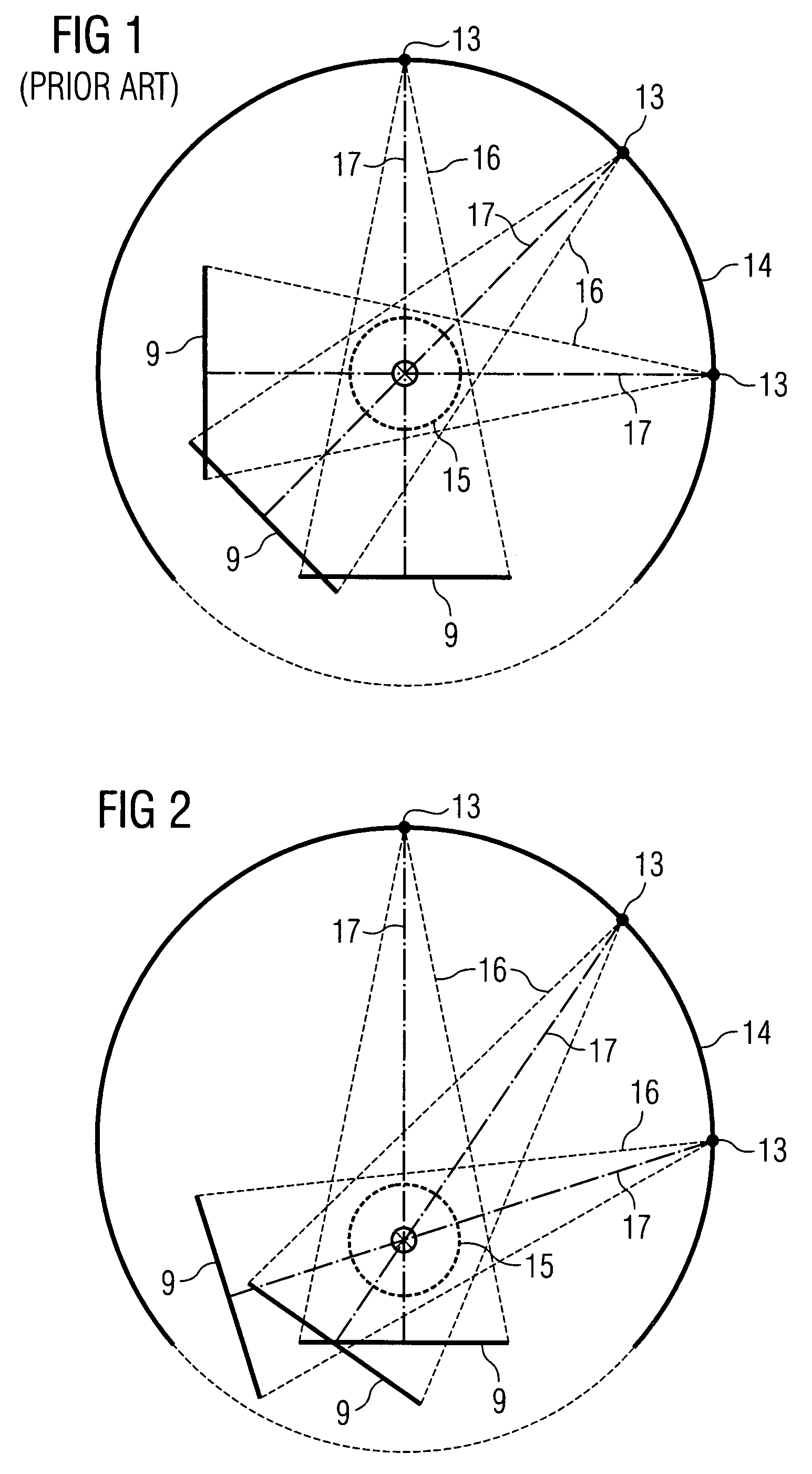
[0023]With regard to known C-arm systems, the rotation of the C-arm with the X-ray tube and the X-ray detector takes place around a fixed rotation center, in which the area of interest of the examination object must also be situated. In this situation, the examination object is usually a patient who is suitably positioned on a patient support. FIG. 1 schematically illustrates such a recording situation in which the X-ray focus 13 of the C-arm system is guided on a segment of a circular path, also referred to in the following as the focus path 14. As a result of the rotation of the support with the X-ray tube around the fixed rotation center the X-ray detector 9 also moves on a corresponding circular path, as indicated in FIG. 1. For error-free image reconstruction the area of interest 15 must, for each projection or X-ray imaging process, lie within the beam cone 16 of the X-ray beam which is emitted by the X-ray focus 13 in the direction of the X-ray detector 9. In this situation, ...


PUM


Abstract

There is described a method using an X-ray imaging unit, which has an arched support for the X-ray source and the X-ray detector. In the method, in a scan carried out by moving the support around an examination object a plurality of X-ray images of an area of interest are recorded using different projection angles, from which a three-dimensional image of the area of interest can be reconstructed. In this case the X-ray focus of the X-ray source is guided on a segment of a circular path of at least 180° around the examination object. In the case of a non-centric location of the area of interest, the support is rotated in such a manner prior to each of the X-ray imaging processes around an axis of rotation passing through the X-ray focus that the central ray of the X-ray beam for the X-ray imaging processes passes through the center of the area of interest.

Description

CROSS REFERENCE TO RELATED APPLICATIONS[0001]This application claims priority of German Patent Office application No. 10 2006 046 692.6 DE filed Sep. 29, 2006, which is incorporated by reference herein in its entirety.FIELD OF INVENTION[0002]The present invention relates to a method for X-ray image recording using an X-ray imaging unit which has an X-ray source and an X-ray detector situated opposite the X-ray source on an arched support, with the result that an X-ray beam emitted from an X-ray focus at the X-ray source strikes the X-ray detector. The method in question is one in which during a scan carried out by moving the support around an examination object positioned between the X-ray source and the X-ray detector a plurality of X-ray images of an area of interest of the examination object are recorded using different projection angles, from which a three-dimensional image of the area of interest can be reconstructed. The invention also relates to an X-ray imaging system which ...

Claims


Application Information

Patent Timeline
Patent Type & Authority Patents(United States)
IPC IPC(8): A61B6/00
CPCA61B6/4441A61B6/466B25J15/0019G03B42/02A61B6/4458G01N23/046G01N2223/419
Inventor ZELLERHOFF, MICHAEL
Owner SIEMENS HEALTHCARE GMBH
Why Eureka
Try Eureka