Electric lock

Inactive Publication Date: 2009-04-14
YEONG DU TRADING
View PDF26 Cites 87 Cited by
  • Summary
  • Abstract
  • Description
  • Claims
  • Application Information

AI Technical Summary

Benefits of technology

[0007]As such, since no friction occurs among rotating parts of the electric lock, wearing of the rotating parts can be prevented,

Problems solved by technology

However, protrusions of rotatable members of the electric lock experience fast wear due to frequent contact therebetween, thereby re

Method used


Image

  • Electric lock
  • Electric lock
  • Electric lock

Examples


Embodiment Construction

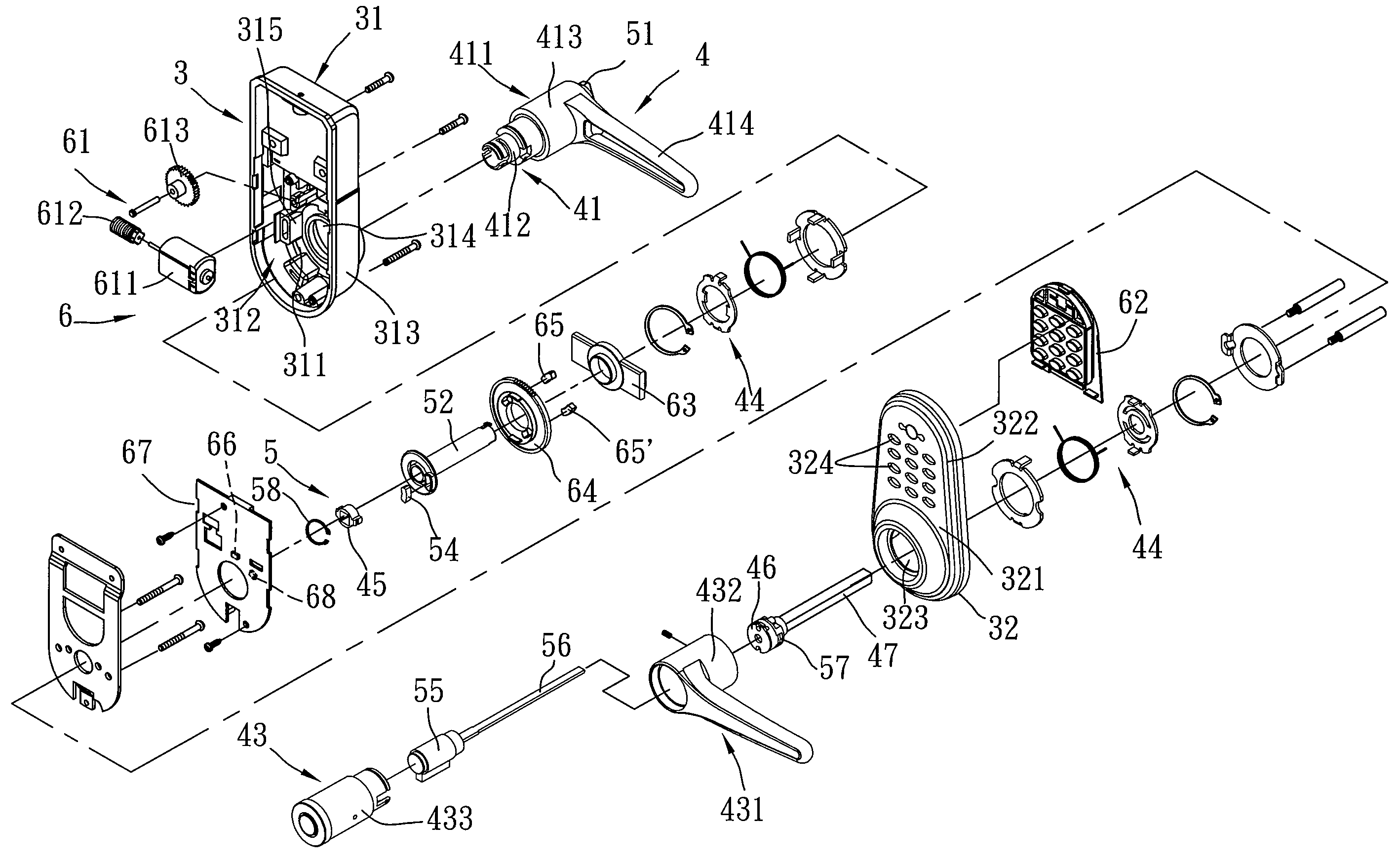
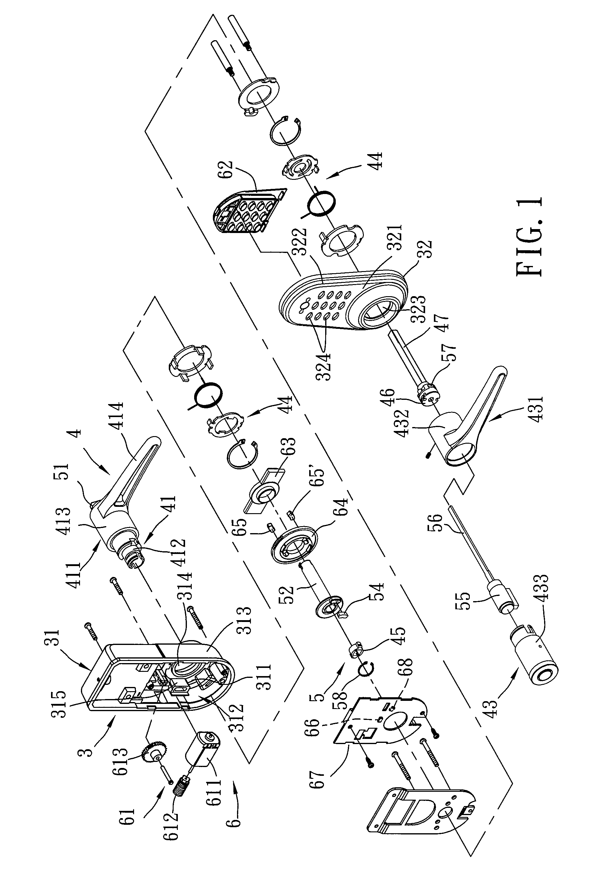
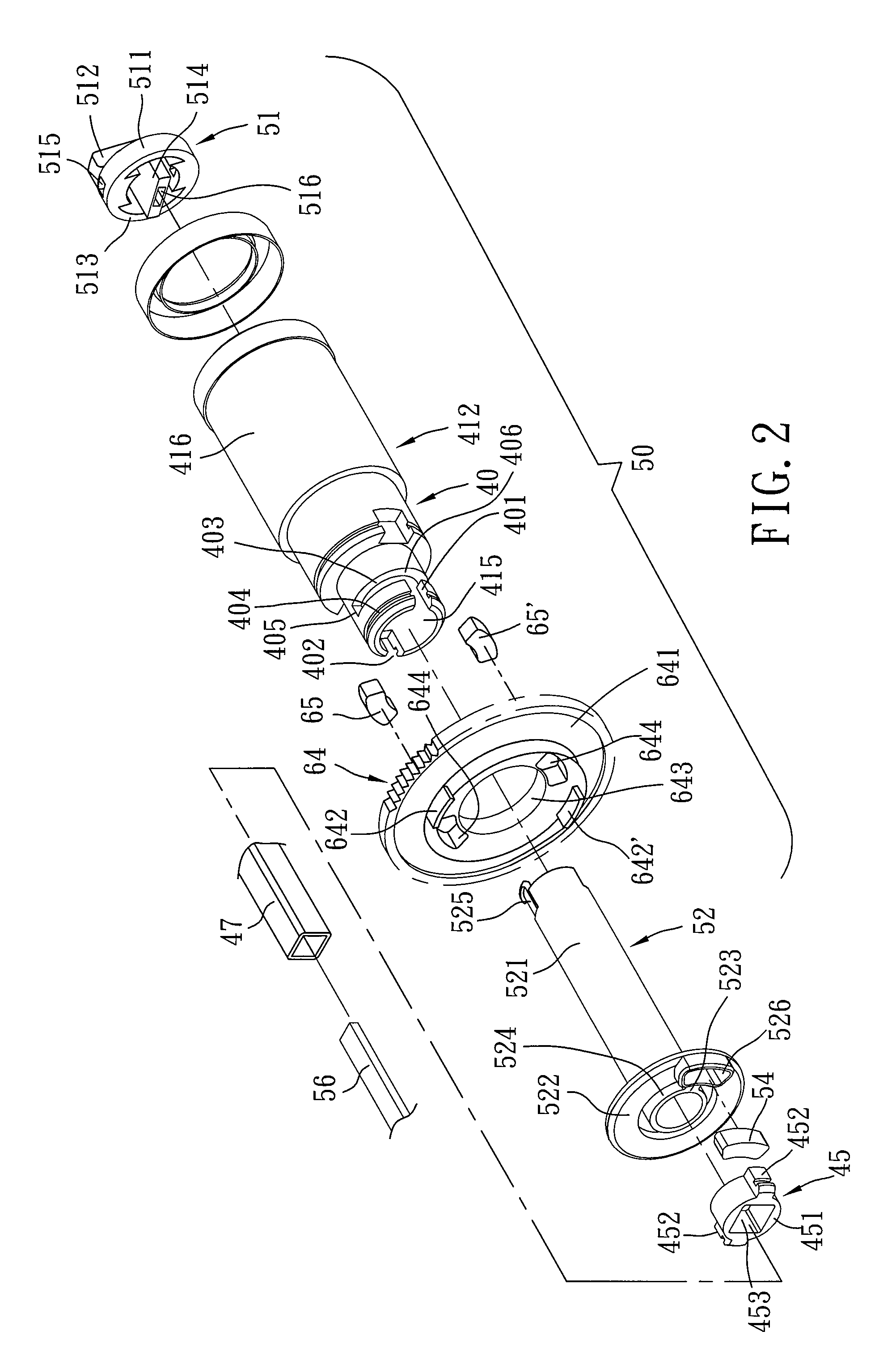
[0017]Referring to FIGS. 1, 2, and 3, the first preferred embodiment of an electric lock according to this invention is mounted to a door (not shown), and includes a lock housing unit 3, a handle unit 4, a manual operation mechanism 5, and an electric control mechanism 6.

[0018]The lock housing unit 3 includes a first lock housing 31 mounted to an inner side surface of the door, and a second lock housing 32 mounted to an outer side surface of the door. The first lock housing 31 has an upright wall 311, and a surrounding wall 313 extending from a periphery of the upright wall 311 toward the door to define an accommodating chamber 312. The upright wall 311 has a circular mounting hole 314 and two mounting blocks 315 (only one is shown in FIG. 1) flanking the mounting hole 314 and extending into the accommodating space 312. The second lock housing 32 has an upright wall 321 and a surrounding wall 322 extending from a periphery of the upright wall 321 toward the door. The upright wall 32...


PUM


Abstract

An electric lock includes a manual operation mechanism and an electric control mechanism. The manual operation mechanism includes a rotary knob unit, a first attracting member mounted fixedly to the rotary knob unit, a key-operated lockset, and a lock-connecting rod connected to and rotatable by the rotary knob unit and the key-operated lockset. The electric control mechanism includes a power source unit, a clutch gear driven by the power source unit to rotate in two directions, and a second attracting member mounted fixedly to the clutch gear. When the clutch gear is driven by the power source unit to rotate to align the first and second attracting members with each other, a magnetic attraction force is generated between the first and second attracting members to allow for co-rotation of the rotary knob unit with the clutch gear.

Description

BACKGROUND OF THE INVENTION[0001]1. Field of the Invention[0002]This invention relates to an electric lock, and more particularly to an electric lock that can be operated either electrically or manually.[0003]2. Description of the Related Art[0004]In US Patent Application Publication No. 2007 / 0169525, the applicant discloses an electric lock operable either electrically or manually to increase convenience during use. However, protrusions of rotatable members of the electric lock experience fast wear due to frequent contact therebetween, thereby reducing the service life of the electric lock. Furthermore, locking and unlocking of the electric lock cannot be controlled precisely.SUMMARY OF THE INVENTION[0005]The object of this invention is to provide an electric lock that is durable and that can be locked and unlocked precisely.[0006]According to this invention, an electric lock includes a manual operation mechanism and an electric control mechanism. The manual operation mechanism inc...

Claims


Application Information

Patent Timeline
IPC IPC(8): E05B13/10
CPCE05B13/101E05B47/068E05B47/0012E05B47/0038E05B2047/002E05B2047/0026E05B2047/0094Y10S292/27Y10T70/5416Y10T70/5673Y10T70/5827Y10T70/5832Y10T70/7057Y10T70/7062Y10T70/7068Y10T70/7107Y10T292/11
Inventor CHANG, JING-CHEN
Owner YEONG DU TRADING
Why Eureka
Try Eureka