Torsion detecting sleeve member and torque-detecting device

a technology of torque detection and sleeve member, which is applied in the direction of force measurement, instruments, cycle equipment, etc., can solve the problems of large measurement errors, reduced detection sensitivity, excessive torque, etc., and achieves improved detection sensitivity, easy detection, and variation in the permeability of the magnetostrictive member

Inactive Publication Date: 2009-04-14
SHIMANO INC
View PDF8 Cites 62 Cited by
  • Summary
  • Abstract
  • Description
  • Claims
  • Application Information

AI Technical Summary

Benefits of technology

[0014]Another object of the present invention is to provide a cylindrical torsion-detecting sleeve member and a torque sensor wherein measurement errors can be prevented even when a large amount of torque is applied.
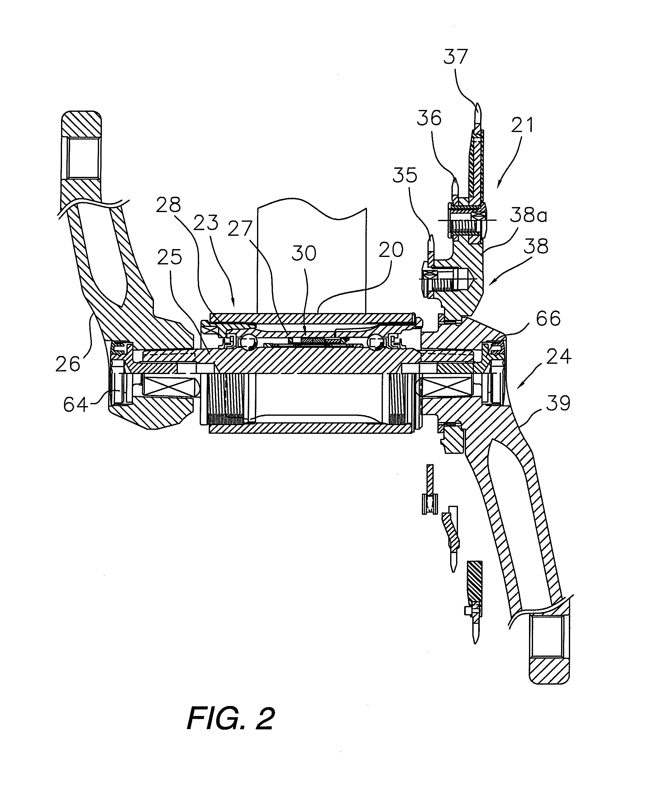
[0028]According to another aspect of the present invention, the amount of torsion transmitted from the first and second cylindrical torque-acting parts to the torsion signal generator is reduced. Therefore, the torsion signal generator is not likely to twist excessively, and errors in measurement can be prevented even when a large amount of torque is applied.

Problems solved by technology

Therefore, the torsion is excessive when a comparatively large amount of torque is detected in the bicycle or the like.
Also the sensitivity of detection may be reduced, leading to large measurement errors.
In the configuration of Japanese Laid-Open Patent Application No. 2001-289720, when a comparatively large amount of torque is detected and the stress acting on the torque transmission shaft exceeds a specified level, the residual stress in the interior of the torque transmission shaft may result in hysteresis, errors in sensor output, and measurement errors.
Thus, in the configurations of the conventional examples, measurement errors may occur when a large amount of torque is applied.
Moreover, the range of torque detection is limited by the thickness or rigidity of the thin cylindrical member or the sleeve even when the amount of torque is small, and it is difficult to vary the range of torque detection.

Method used


Image

  • Torsion detecting sleeve member and torque-detecting device
  • Torsion detecting sleeve member and torque-detecting device
  • Torsion detecting sleeve member and torque-detecting device

Examples


second embodiment

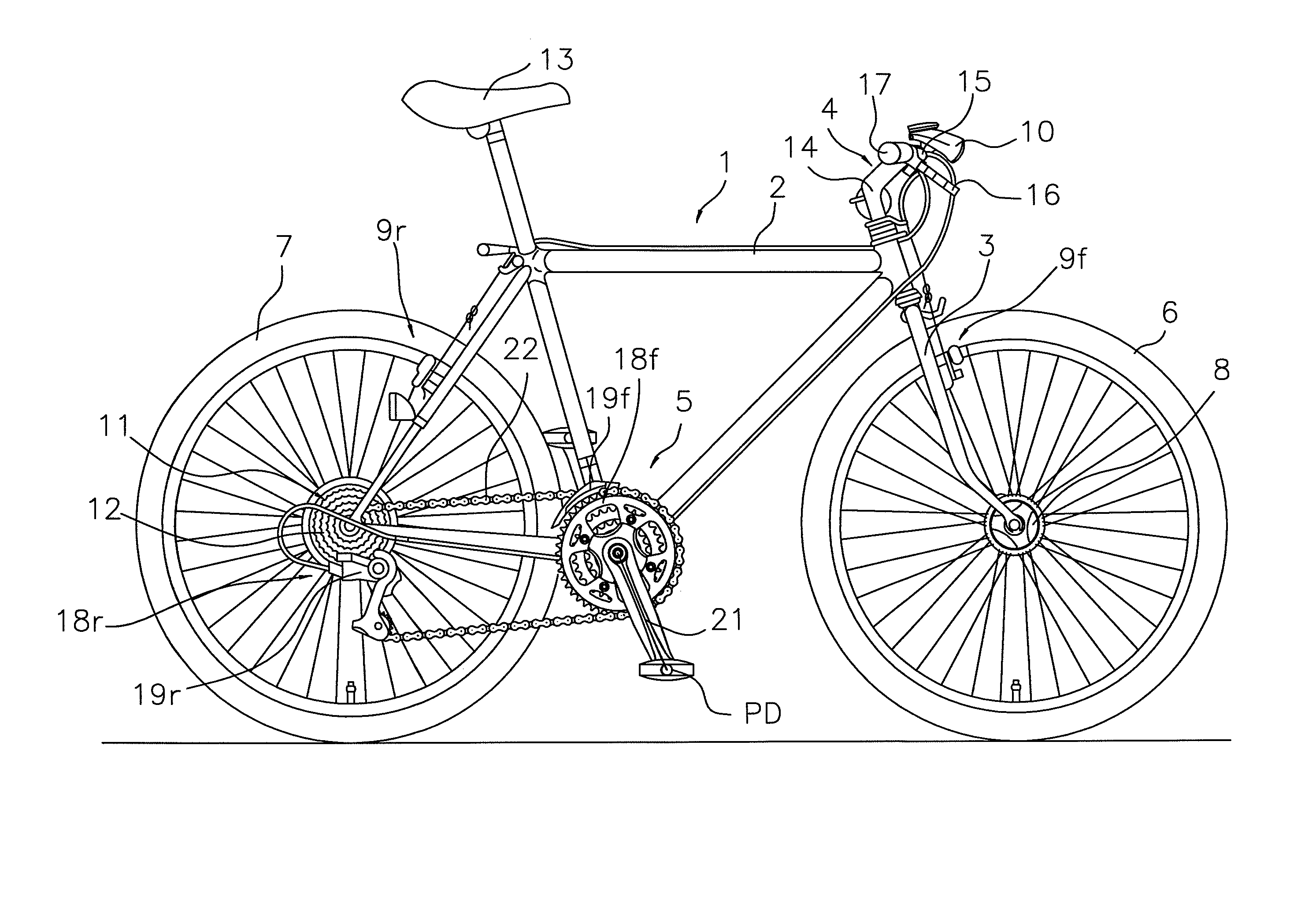
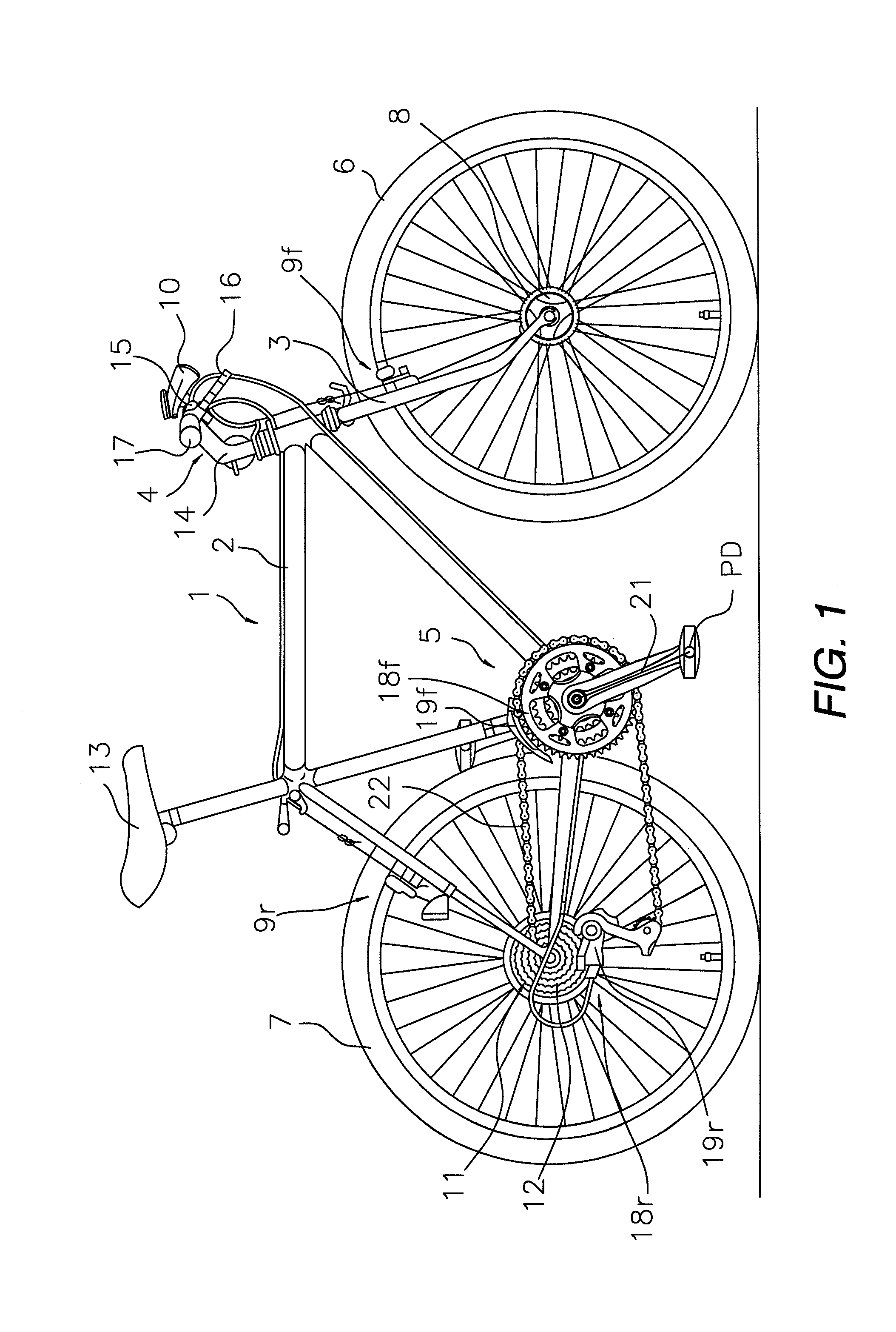
[0067]Referring now to FIGS. 7 to 10, a modified crank assembly 121 will now be explained in accordance with a second embodiment. The modified crank assembly 121 is installed into the hanger part 20. In view of the similarity between the first and second embodiments, the descriptions of the parts of the second embodiment that are identical to the parts of the first embodiment may be omitted for the sake of brevity.

[0068]In the first embodiment, the present invention described using the crank assembly 21 as an example, wherein the gear crank 24 and the left crank 26 were detachably fastened to both ends of the solid crank axle 25 with the aid of the fastening bolts 66 and 64. In the second embodiment, an embodiment is described in which the crank assembly 121 has a crank shaft assembly 123 with a gear crank 124 integrally fastened to one end of a crank axle 125, as shown in FIG. 7. The crank axle 125 is also integrally fastened to a left crank 126. In particular, the gear crank 124 i...


PUM

PropertyMeasurementUnit
cylindrical torqueaaaaaaaaaa
magnetostrictiveaaaaaaaaaa
rotational torqueaaaaaaaaaa

Abstract

A torque-detecting sleeve member is a cylindrical member that has first and second cylindrical torque-acting parts, a torsion signal generator and a torsion converter. Torque acts on the first and second cylindrical torque-acting parts in at least two points. The torsion signal generator is disposed axially between the first and second cylindrical torque-acting parts to at least partially form an external peripheral surface between the first and second cylindrical torque-acting parts. The torsion converter is operatively disposed between the torsion signal generator and at least one of the first and second cylindrical torque-acting parts for converting torsion transmitted from the at least one of the first and second cylindrical torque-acting parts to the torsion signal generator.

Description

CROSS-REFERENCE TO RELATED APPLICATIONS[0001]This application claims priority under 35 U.S.C. § 119 to Japanese Patent Application No. 2007-097596, filed Apr. 3, 2007. The entire disclosure of Japanese Patent Application No. 2007-097596 is hereby incorporated herein by reference.BACKGROUND OF THE INVENTION[0002]1. Field of the Invention[0003]This invention generally relates to a cylindrical torsion-detecting sleeve member. More specifically, the present invention relates to a torque-detecting device that uses the sleeve member.[0004]2. Background Information[0005]Bicycling is becoming an increasingly more popular form of recreation as well as a means of transportation. Moreover, bicycling has become a very popular competitive sport for both amateurs and professionals. Whether the bicycle is used for recreation, transportation or competition, the bicycle industry is constantly improving the various components of the bicycle. Recently, bicycles have been provided with cycle computers ...

Claims


Application Information

Patent Timeline
Patent Type & Authority Patents(United States)
IPC IPC(8): G01L3/02
CPCG01L3/102B62J45/411B62J45/421
Inventor WATARAI, ETSUYOSHIHORIUCHI, NORIYUKI
Owner SHIMANO INC
Why Eureka
Try Eureka