

Electrophoretic buffer
a technology of electrophoresis and electrophoresis method, applied in the direction of fluid pressure measurement, liquid/fluent solid measurement, peptide measurement, etc., can solve the problems of difficult injection, and high temperature sensitive viscosity of the buffer, so as to achieve rapid separation of polymer compound and high separation ability
Inactive Publication Date: 2009-04-14
JAPAN SCI & TECH CORP
View PDF8 Cites 0 Cited by
- Summary
- Abstract
- Description
- Claims
- Application Information
AI Technical Summary
Benefits of technology
[0004]An object of the present invention is to provide an electrophoretic buffer and an electrophoresis method, which is capable of separating a polymer compound rapidly and at high separation ability.
Problems solved by technology
However, since a polymer having a high viscosity (methylcellulose, hydroxylcellulose, polyacrylamide or the like) is used as a buffer, there are some defects 1) that it takes time to inject the buffer into a microchannel, 2) that the injection becomes more difficult, as a channel width becomes narrower, 3) that it is necessary to change a polymer concentration depending on a size of a DNA, and there is a limitation of a separation degree to separation of a wide range of a DNA size, 4) that viscosity of the buffer is sensitive to temperature, and the like.
Method used
View moreImage
Smart ImageViewing Examples

Examples
example 1
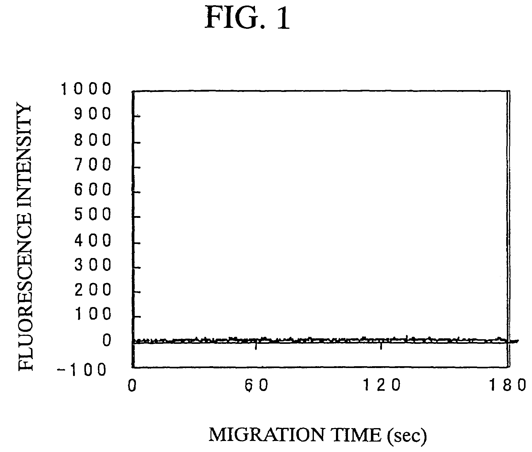
[0149]Using the polymer micelle as an electrophoretic buffer, separation of two DNA markers (100 bp and 800 bp) was carried out by electrophoresis in accordance with the usual method. As a result, a peak did not appear within the migration time of 180 seconds (FIG. 1).
example 2
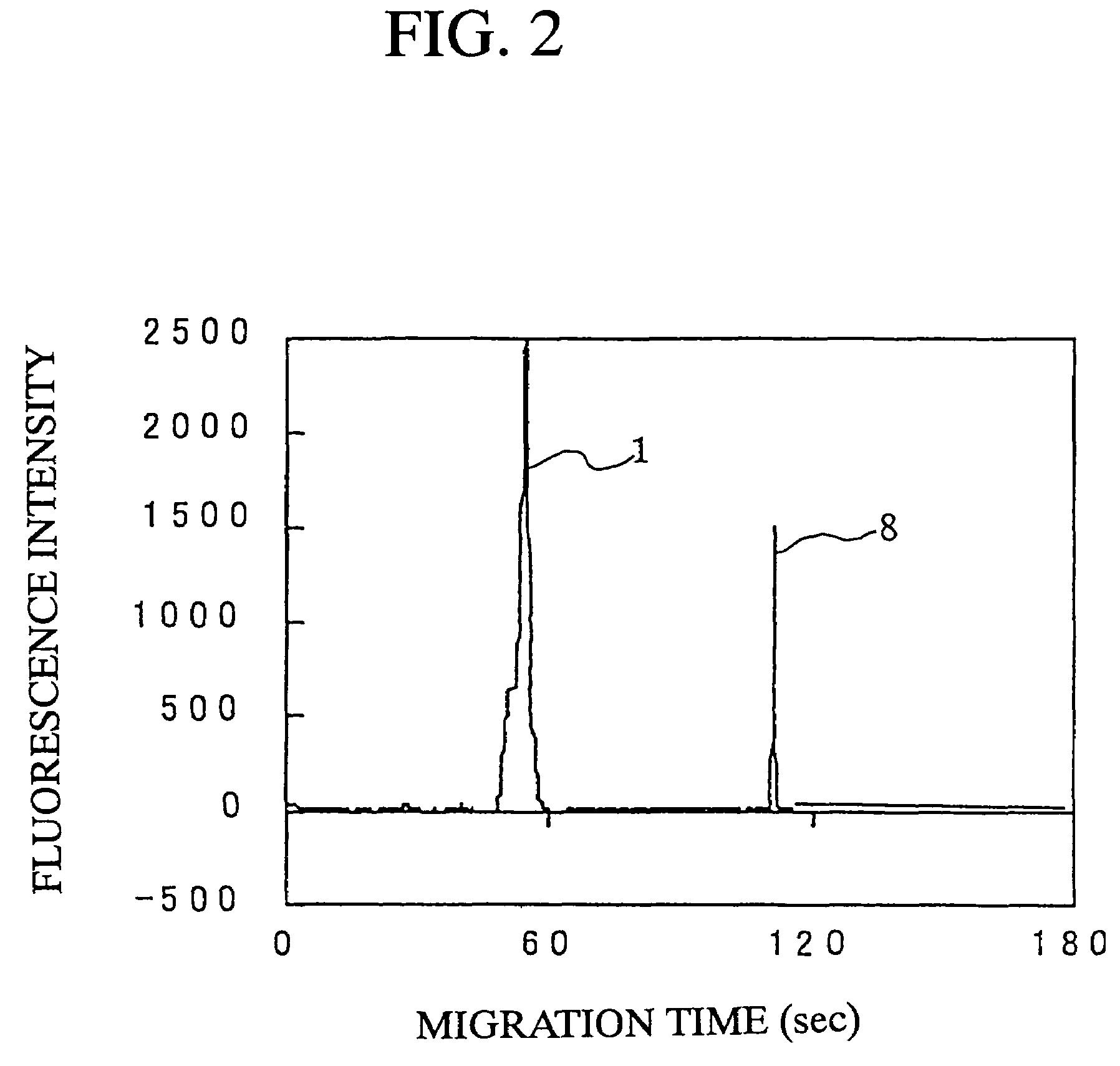
[0150]Example 1 was carried out in accordance with the PP method. An intensity of the former P was M, and an intensity of the latter P was L. As a result, two peaks were found within the migration time of 180 seconds (FIG. 2).
example 3
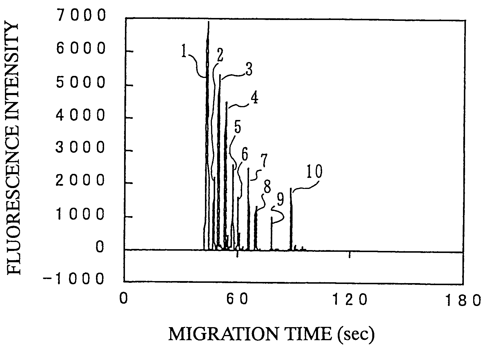
[0151]An intensity of the former P of Example 2 was M, and an intensity of the latter P was M. As a result, the migration time of 100 bp was accelerated (FIG. 3).
Login to View More PUM
| Property | Measurement | Unit |
|---|---|---|
| Time | aaaaa | aaaaa |
| Time | aaaaa | aaaaa |
| Time | aaaaa | aaaaa |
Abstract
By using an electrophoretic buffer comprising a polymerized polymer micelle formed by the steps comprising dispersing into an aqueous medium a block copolymer represented by HPLS-HPBS-PLZA, wherein HPLS is a hydrophilic polymer segment, HPBS is a hydrophobic polymer segment, and PLZA is a polymerizable group having an ethylenically unsaturated double bond, and polymerizing the block copolymer as a buffer for a capillary electrophoresis or a microchip electrophoresis, pressurizing the sample after introduction at a given pressure for a given time period, and electrophoresing in an electrophoretic electric field, a polymer compound such as DNA can be separated rapidly and in high separation ability.
Description
[0001]This application is a 371 of PCT / JP03 / 02969, filed on Mar. 13, 2003, which claims foreign priority from Japanese application 2002-72412, filed on Mar. 15, 2002.TECHNICAL FIELD[0002]The present invention relates to an electrophoretic buffer and an electrophoresis method, which is capable of separating a polymer compound rapidly and at high separation ability.BACKGROUND ART[0003]The existing electrophoretic buffer is excellent in separation ability to a limited size. However, since a polymer having a high viscosity (methylcellulose, hydroxylcellulose, polyacrylamide or the like) is used as a buffer, there are some defects 1) that it takes time to inject the buffer into a microchannel, 2) that the injection becomes more difficult, as a channel width becomes narrower, 3) that it is necessary to change a polymer concentration depending on a size of a DNA, and there is a limitation of a separation degree to separation of a wide range of a DNA size, 4) that viscosity of the buffer is...
Claims
Login to View More Application Information
Patent Timeline
 IPC IPC(8): G01N27/447
CPCG01N27/44747Y10T436/108331B82B1/00G01N27/447
InventorBABA, YOSHINOBUKATAOKA, KAZUNORITABUCHI, MARINAGASAKI, YUKIOTANAKA, YASUKOKUWAHARA, CHIE
OwnerJAPAN SCI & TECH CORP