
Method for making an optical fiber preform via internal vapor deposition

a manufacturing method and technology of optical fiber, applied in the field of manufacturing optical fiber preforms via internal vapor deposition, can solve the problems of uniform optical and/or geometric properties of optical preforms, axially non-uniform cross-section of cores, and lack of geometric and optical uniformity of optical preforms

Active Publication Date: 2009-04-14
DRAKA COMTEQ BV
View PDF14 Cites 8 Cited by
  • Summary
  • Abstract
  • Description
  • Claims
  • Application Information

AI Technical Summary

Benefits of technology

[0016]Accordingly, it is an aspect of the present invention to provide a method for manufacturing an optical preform via an internal vapor deposition process in which both the geometric taper and the optical taper are reduced if not minimized.
[0017]It is another aspect of the present invention to provide a method for manufacturing, via an internal vapor deposition process (e.g., PCVD), an optical preform from which a single mode optical fiber (kind, core, inner and outer cladding) having a stable cut-off wavelength can be produced.
[0018]It is yet another aspect of the present invention to provide a method for manufacturing an optical preform via an internal vapor deposition process, wherein the layers deposited on the interior of the substrate tube have constant diameter over the length of the substrate tube, such that the negative influence of OH-groups in the area at the outer side of the deposited layers is minimized.
[0022]In this regard and with reference to FIG. 1, compared with a conventional cladding deposition (segment BX), at the supply side of the substrate tube, the outer cladding deposition follows a relatively longer ramp (segment BC) whereas the inner cladding deposition follows a relatively shorter ramp (segment BD). In effect, as compared with conventional processes, the present invention achieves improved optical properties in the inner cladding by increasing the acceleration (i.e., segment BD) during deposition of the inner cladding.
[0024]The geometric taper of the inner cladding that occurs therewith is compensated by the special deposition conditions of the outer cladding. In this regard, the present invention achieves satisfactory geometry by decreasing the acceleration (i.e., segment BC) during deposition of the outer cladding. In effect, the initial deposition of the outer cladding compensates for the geometric taper of the inner cladding before the deposition of the inner cladding.
[0026]The present inventors have furthermore found that the effect of a substantially constant ratio b / a on attenuation—particularly the attenuation at a wavelength of 1385 nanometers, which is ascribed to the influence of OH-groups—is practically constant over the length of the preform. At the same time, the stability of the cut-off wavelength over the length of the substrate tube is improved. Based on the perception that it is desirable to optimize the inner cladding for optical parameters and to subsequently compensate the resulting geometric taper of the inner cladding with a geometric taper of the outer cladding, it has appeared to be possible to maintain a constant value for the ratio b / a over substantially the entire length of the substrate tube.

Problems solved by technology

These methods, however, yield optical preforms lacking geometric and optical uniformity.
Such a taper would lead to an axially non-uniform cross-section of the core after an optical fiber has been drawn from the preform.
In particular, the taper forms an area in which the optical and / or geometric properties of the preform are not uniform.
Such non-uniformity will lead to degradation of the transmission qualities of the optical fiber.
Such taper areas in the preform cannot be used to manufacture quality optical fiber and, consequently, that portion of the preform becomes waste (as is any optical fiber drawn therefrom).
Because such taper areas make up a significant part of the preform tube, the total fiber length that can be obtained from a preform is rather limited.

Method used


Image

  • Method for making an optical fiber preform via internal vapor deposition
  • Method for making an optical fiber preform via internal vapor deposition
  • Method for making an optical fiber preform via internal vapor deposition

Examples


Embodiment Construction

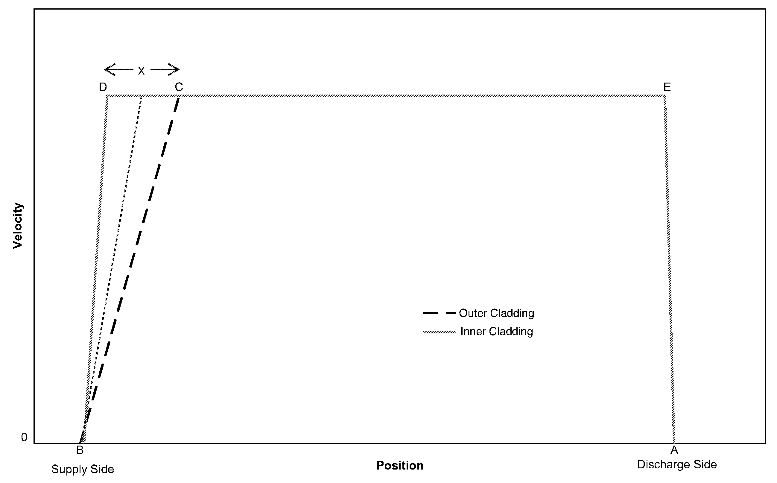
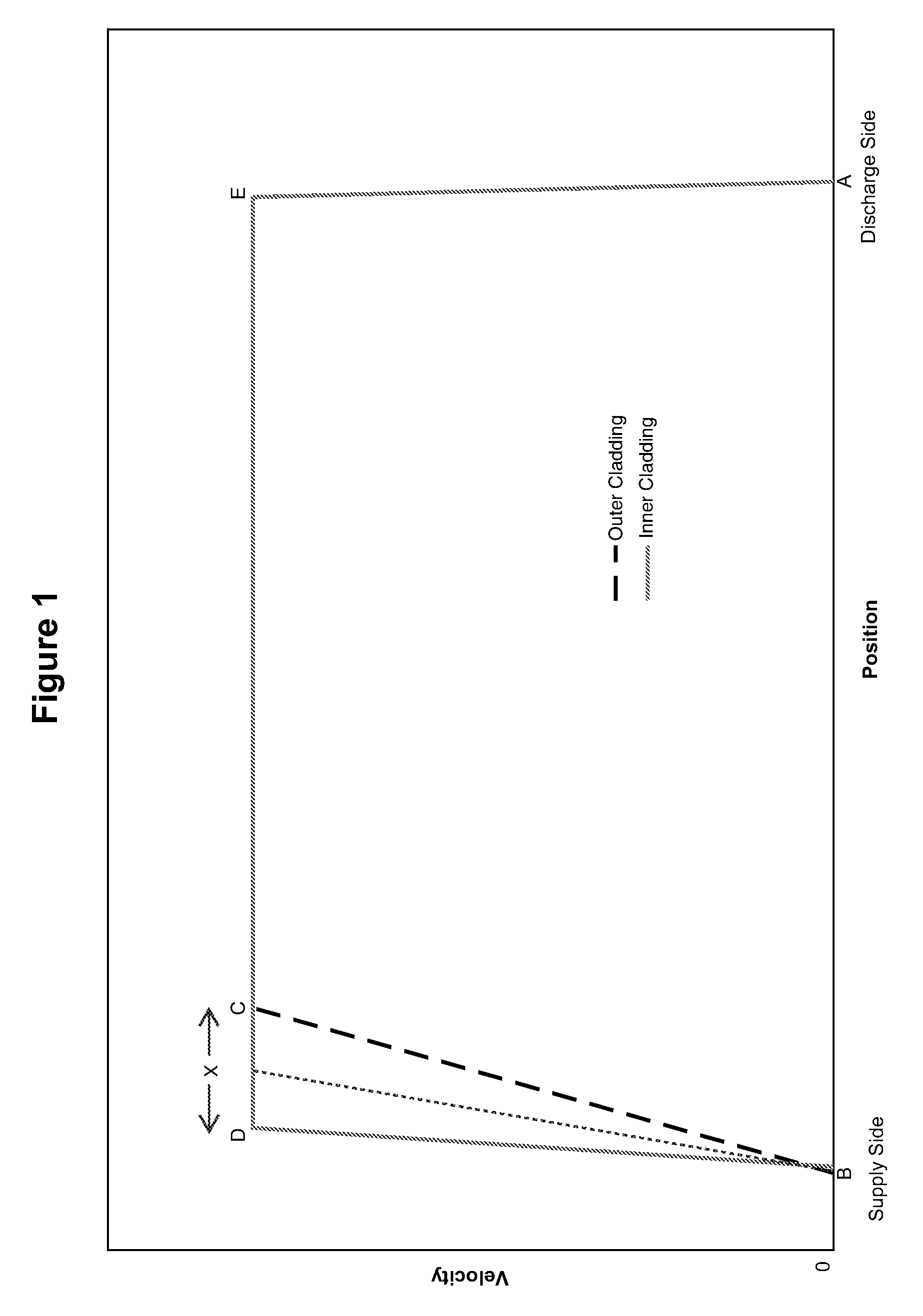
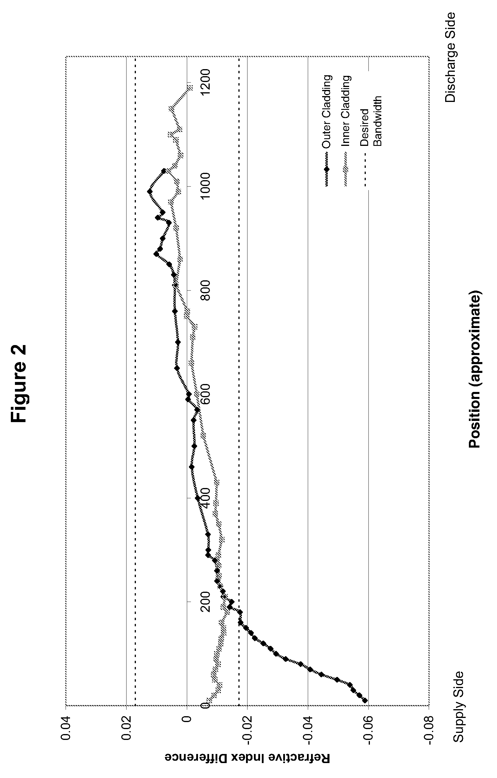
[0046]In one aspect, the present invention embraces a method for manufacturing an optical preform via an internal vapor deposition process in a way that significantly improves optical taper in the inner cladding and yet maintains acceptable preform geometry.

[0047]As compared with prior methods, the process according to the present invention achieves a meaningful improvement in manufacturing efficiency and yield (i.e., less waste). For example, the present invention as described herein yields a glass substrate tube whose glass-deposition region (i.e., the interior region onto which glass layers are deposited) may be used at a high efficiency (e.g., 70-75 percent or more) to manufacture quality optical fibers (i.e., possessing satisfactory geometric and optical properties). Those having ordinary skill in the art will appreciate that the glass-deposition region is defined by the shortest glass layer (e.g., the core) deposited on the interior of the glass substrate tube and thus typical...


PUM

PropertyMeasurementUnit
outer diameteraaaaaaaaaa
lengthaaaaaaaaaa

Abstract

The present invention relates to a method for manufacturing an optical preform by employing an internal vapor deposition process. The method uses an energy source and a substrate tube, wherein the energy source is movable over the length of the substrate tube between a point of a reversal at the supply side and a point of a reversal at the discharge side.

Description

CROSS-REFERENCE TO PRIORITY APPLICATION[0001]This application hereby claims the benefit of pending Dutch Application No. 1,032,140 (filed Jul. 10, 2006, at the Netherlands Industrial Patent Office), which is hereby incorporated by reference in its entirety.FIELD OF THE INVENTION[0002]The present invention relates to a method for manufacturing an optical preform via internal vapor deposition.BACKGROUND OF THE INVENTION[0003]Methods for making an optical preform via vapor deposition are known. These methods, however, yield optical preforms lacking geometric and optical uniformity.[0004]One such method, for example, is disclosed in U.S. Pat. No. 4,741,747. This patent identifies as important deposition parameters reproducibility, the yield of the chemical reaction between the glass-forming precursors, and the deposition rate and the optical and geometric homogeneity of the material deposited on the interior of the substrate tube.[0005]During the deposition process, however, so-called “...

Claims


Application Information

Patent Timeline
Patent Type & Authority Patents(United States)
IPC IPC(8): G02B6/02
CPCC03B37/01815G02B6/03622Y02P40/57
Inventor TERPSMA, JELLE PHILIPDECKERS, ROB HUBERTUS MATHEUS
Owner DRAKA COMTEQ BV
Learn More