Technique for accelerating log replay with partial cache flush
Active Publication Date: 2009-04-14
NETWORK APPLIANCE INC
33 Cites 100 Cited by
AI-Extracted Technical Summary
Problems solved by technology
If an additional crash occurs soon after finishing the undo phase cache flush, ...
View moreMethod used
[0037]FIG. 3 is a schematic block diagram illustrating the storage subsystem 300 that may be advantageously used with the present invention. Storage of information on the storage subsystem 300 is illustratively implemented as a plurality of storage disks 310 defining an overall logical arrangement of disk space. The disks are further organized as one or more groups or sets of Redundant Array of Independent (or Inexpensive) Disks (RAID). RAID implementations enhance the reliability/integrity of data storage through the writing of data “stripes” across a given number of physical disks in the RAID group, and the appropriate storing of redundant information with respect to the striped data. The redundant information enables recovery of data lost when a storage device fails. It will be apparent to those skilled in the art that other redundancy techniques, such as mirroring, may used in accordance with the present invention.
[0041]To facilitate access to the disks 310 and information stored thereon, the storage operating system 400 implements a write-anywhere file system, such as the SpinFS file system, which logically organizes the information as a hierarchical structure of named directories and files on the disks. However, it is expressly contemplated that any appropriate storage operating system, including a write in-place file system, may be enhanced for use in accordance with the inventive principles described herein. Each “on-disk” file may be implemented as set of disk blocks configured to store information, such as data, whereas the directory may be implemented as a specially formatted file in which names and links to other files and directories are stored.
[0054]The VLDB 830 is a database process that tracks the locations of various storage components (e.g., a VFS) withi...
View moreBenefits of technology
[0013]The present invention overcomes the disadvantages of the prior art by providing a technique for replaying a file system log file with partial flushing of a cache in a storage system to enable clients to obtain access to their data in a more expedient manner. The novel technique distinguishes between “redo” transactions and “undo” transactions and replays these transactions in multiple phases, a (i) a pre-processing phase, (ii) a redo phase, and (iii) an undo phase. The pre-processing phase performs various integrity checks and determines which portions of the log need to be replayed. The redo phase replays those transactions that were committed to the log prior to the crash. The undo phase rolls back those transactions that were not yet committed at the time of the crash.
[0014]Once the undo phase has completed, only the data dirtied during the undo phase is flushed from the cache to disk. If a transaction was undone during the undo phase, the technique writes any data that was modified to disk during the undoing of the transaction. As very few transactions are typically pending at t...
View moreAbstract
A system and method for replaying a log file without performing a total cache flush. The log replay is performed in three phases, a pre-processing phase that determines which portions of the log file are to be replayed, a redo phase where certain transactions are redone and an undo phase where certain transactions are rolled back. After performing the log replay only the data dirtied during the undo phase is flushed from the cache, thereby decreasing the amount of time required for the log replay operation.
Application Domain
Technology Topic
Image
Examples
- Experimental program(1)
Example
[0029]A. Cluster Environment
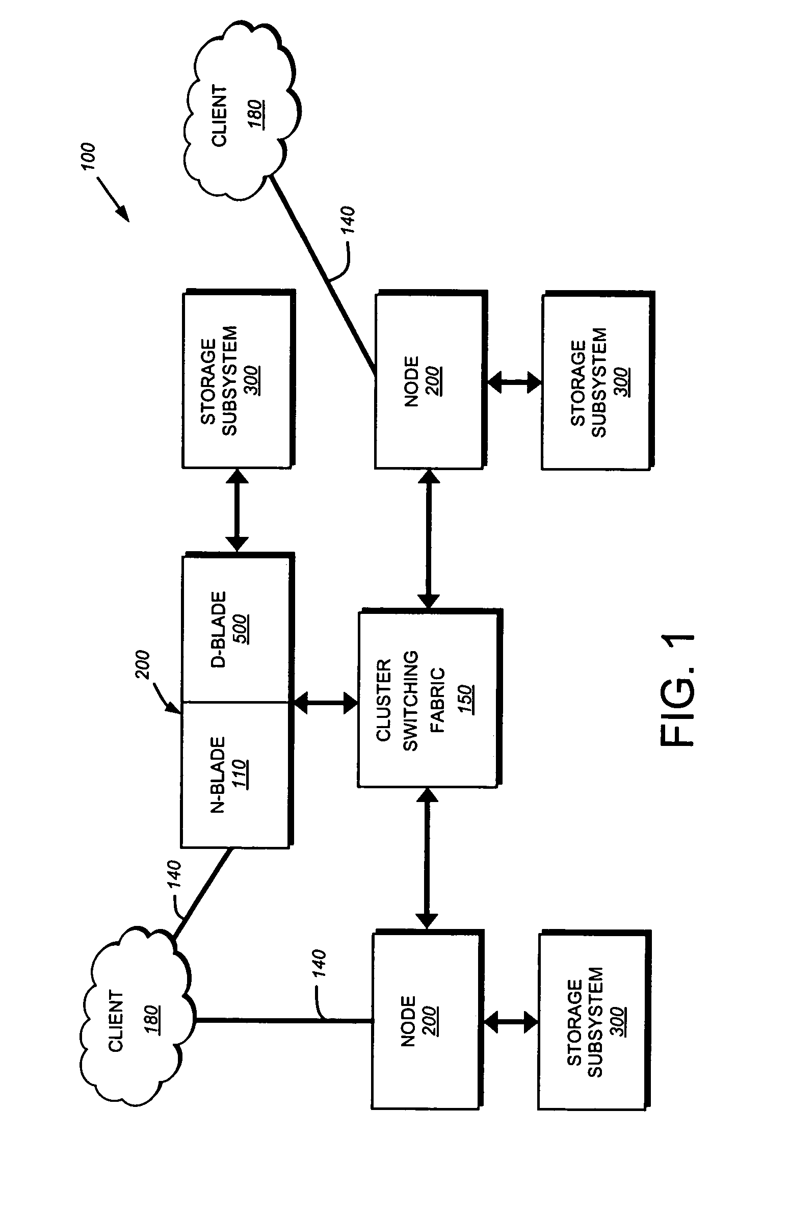
[0030]FIG. 1 is a schematic block diagram of a plurality of nodes 200 interconnected as a cluster 100 and configured to provide storage service relating to the organization of information on storage devices of a storage subsystem. The nodes 200 comprise various functional components that cooperate to provide a distributed Spin File System (SpinFS) architecture of the cluster 100. To that end, each SpinFS node 200 is generally organized as a network element (N-blade 110) and a disk element (D-blade 500). The N-blade 110 includes a plurality of ports that couple the node 200 to clients 180 over a computer network 140, while each D-blade 500 includes a plurality of ports that connect the node to a storage subsystem 300. The nodes 200 are interconnected by a cluster switching fabric 150 which, in the illustrative embodiment, may be embodied as a Gigabit Ethernet switch. The distributed SpinFS architecture is generally described in U.S. Patent Application Publication No. US 2002/0116593 titled Method and System for Responding to File System Requests, by M. Kazar et al. published Aug. 22, 2002.
[0031]B. Storage Systems
[0032]FIG. 2 is a schematic block diagram of a node 200 that is illustratively embodied as a storage system server comprising a plurality of processors 222, a memory 224, a network adapter 225, a cluster access adapter 226, a local storage and a storage adapter 228 interconnected by a system bus 223. The local storage is utilized by the node to store local configuration information (i.e. management data), including its local copy of a replicated database (RDB) 850 (see FIG. 8). The cluster access adapter 226 comprises a plurality of ports adapted to couple the node 200 to other nodes of the cluster 100. In the illustrative embodiment, Ethernet is used as the clustering protocol and interconnect media, although it will be apparent to those skilled in the art that other types of protocols and interconnects may be utilized within the cluster architecture described herein.
[0033]Each node 200 is illustratively embodied as a dual processor server system executing a storage operating system 400 that provides a file system configured to logically organize the information as a hierarchical structure of named directories and files on storage subsystem 300. However, it will be apparent to those of ordinary skill in the art that the node 200 may alternatively comprise a single or more than two processor system. Illustratively, one processor 222a executes the functions of the N-blade 110 on the node, while the other processor 222b executes the functions of the D-blade 500. It should be noted that a node may comprise any number of N and D-blades. As such, the description of a node having one N-blade and one D-blade should be taken as exemplary only.
[0034]In the illustrative embodiment, the memory 224 comprises storage locations that are addressable by the processors and adapters for storing software program code and data structures, such as log file 900, associated with the present invention. The processor and adapters may, in turn, comprise processing elements and/or logic circuitry configured to execute the software code and manipulate the data structures. The storage operating system 400, portions of which are typically resident in memory and executed by the processing elements, functionally organizes the node 200 by, inter alia, invoking storage operations in support of the storage service implemented by the node. It will be apparent to those skilled in the art that other processing and memory means, including various computer readable media, may be used for storing and executing program instructions pertaining to the inventive system and method described herein.
[0035]The network adapter 225 comprises a plurality of ports adapted to couple the node 200 to one or more clients 180 over point-to-point links, wide area networks, virtual private networks implemented over a public network (Internet) or a shared local area network, hereinafter referred to as an Ethernet computer network 140. Therefore, the network adapter 225 may comprise a network interface card (NIC) having the mechanical, electrical and signaling circuitry needed to connect the node to the network. For such a network attached storage (NAS) based network environment, the clients are configured to access information stored on the node 200 as files. The clients 180 communicate with each node over network 140 by exchanging discrete frames or packets of data according to pre-defined protocols, such as the Transmission Control Protocol/Internet Protocol (TCP/IP).
[0036]The storage adapter 228 cooperates with the storage operating system 400 executing on the node 200 to access information requested by the clients. The information may be stored on disks or other similar media adapted to store information. The storage adapter comprises a plurality of ports having input/output (I/O) interface circuitry that couples to the disks over an I/O interconnect arrangement, such as a conventional high-performance, Fibre Channel (FC) link topology. The information is retrieved by the storage adapter and, if necessary, processed by the processor 222 (or the adapter 228 itself) prior to being forwarded over the system bus 223 to the network adapter 225 where the information is formatted into packets or messages and returned to the clients.
[0037]FIG. 3 is a schematic block diagram illustrating the storage subsystem 300 that may be advantageously used with the present invention. Storage of information on the storage subsystem 300 is illustratively implemented as a plurality of storage disks 310 defining an overall logical arrangement of disk space. The disks are further organized as one or more groups or sets of Redundant Array of Independent (or Inexpensive) Disks (RAID). RAID implementations enhance the reliability/integrity of data storage through the writing of data “stripes” across a given number of physical disks in the RAID group, and the appropriate storing of redundant information with respect to the striped data. The redundant information enables recovery of data lost when a storage device fails. It will be apparent to those skilled in the art that other redundancy techniques, such as mirroring, may used in accordance with the present invention.
[0038]Each RAID set is illustratively configured by one or more RAID controllers 330. The RAID controller 330 exports a RAID set as a logical unit number (LUN 320) to the D-blade 500, which writes and reads blocks to and from the LUN 320. One or more LUNs are illustratively organized as a storage pool 350, wherein each storage pool 350 is “owned” by a D-blade 500 in the cluster 100. Each storage pool 350 is further organized as a plurality of virtual file systems (VFSs 380), each of which is also owned by the D-blade. Each VFS 380 may be organized within the storage pool according to a hierarchical policy that, among other things, allows the VFS to be dynamically moved among nodes of the cluster to, for example, control load among individual storage pools.
[0039]In the illustrative embodiment, a VFS 380 is synonymous with a volume and comprises a root directory, as well as a number of subdirectories and files. A group of VFSs may be composed into a larger namespace. For example, a root directory (c:) may be contained within a root VFS (“/”), which is the VFS that begins a translation process from a pathname associated with an incoming request to actual data (file) in a file system, such as the SpinFS file system. The root VFS may contain a directory (“system”) or a mount point (“user”). A mount point is a SpinFS object used to “vector off” to another VFS and which contains the name of that vectored VFS. The file system may comprise one or more VFSs that are “stitched together” by mount point objects.
[0040]C. Storage Operating System
[0041]To facilitate access to the disks 310 and information stored thereon, the storage operating system 400 implements a write-anywhere file system, such as the SpinFS file system, which logically organizes the information as a hierarchical structure of named directories and files on the disks. However, it is expressly contemplated that any appropriate storage operating system, including a write in-place file system, may be enhanced for use in accordance with the inventive principles described herein. Each “on-disk” file may be implemented as set of disk blocks configured to store information, such as data, whereas the directory may be implemented as a specially formatted file in which names and links to other files and directories are stored.
[0042]As used herein, the term “storage operating system” generally refers to the computer-executable code operable on a computer that manages data access and may, in the case of a node 200, implement data access semantics of a general purpose operating system. The storage operating system can also be implemented as a microkernel, an application program operating over a general-purpose operating system, such as UNIX® or Windows NT®, or as a general-purpose operating system with configurable functionality, which is configured for storage applications as described herein.
[0043]In addition, it will be understood to those skilled in the art that the inventive system and method described herein may apply to any type of special-purpose (e.g., storage serving appliance) or general-purpose computer, including a standalone computer or portion thereof, embodied as or including a storage system. Moreover, the teachings of this invention can be adapted to a variety of storage system architectures including, but not limited to, a network-attached storage environment, a storage area network and disk assembly directly-attached to a client or host computer. The term “storage system” should therefore be taken broadly to include such arrangements in addition to any subsystems configured to perform a storage function and associated with other equipment or systems.
[0044]FIG. 4 is a partial schematic block diagram of the storage operating system 400 that may be advantageously used with the present invention. The storage operating system comprises a series of software layers organized to form an integrated network protocol stack 430 that provides a data path for clients to access information stored on the node 200 using file access protocols. The protocol stack includes a media access layer 410 of network drivers (e.g., gigabit Ethernet drivers) that interfaces to network protocol layers, such as the IP layer 412 and its supporting transport mechanisms, the TCP layer 414 and the User Datagram Protocol (UDP) layer 416. A file system protocol layer provides multi-protocol file access to a file system 450 (the SpinFS file system) and, thus, includes support for the CIFS protocol 420 and the NFS protocol 422. As described further herein, a plurality of management processes executes as user mode applications 800.
[0045]In the illustrative embodiment, the processors 222 share various resources of the node 200, including the storage operating system 400. To that end, the N-blade 110 executes the integrated network protocol stack 430 of the operating system 400 to thereby perform protocol termination with respect to a client issuing incoming NFS/CIFS file access request packets over the network 150. The NFS/CIFS layers of the network protocol stack function as NFS/CIFS servers 422, 420 that translate NFS/CIFS requests from a client into SpinFS protocol requests used for communication with the D-blade 500. The SpinFS protocol is a file system protocol that provides operations related to those operations contained within the incoming file access packets. Local communication between an N-blade and D-blade of a node is preferably effected through the use of message passing between the blades, while remote communication between an N-blade and D-blade of different nodes occurs over the cluster switching fabric 150.
[0046]D. D-Blade
[0047]Specifically, the NFS and CIFS servers of an N-blade 110 convert the incoming file access requests into SpinFS requests that are processed by the D-blades 500 of the cluster 100. Each D-blade 500 provides a disk interface function through execution of the SpinFS file system 450. In the illustrative cluster 100, the file systems 450 cooperate to provide a single SpinFS file system image across all of the D-blades in the cluster. Thus, any network port of an N-blade that receives a client request can access any file within the single file system image located on any D-blade 500 of the cluster. FIG. 5 is a schematic block diagram of the D-blade 500 comprising a plurality of functional components including a file system processing module (the inode manager 502), a logical-oriented block processing module (the Bmap module 504) and a Bmap volume module 506. The inode manager 502 is the processing module that implements the SpinFS file system 450, whereas the Bmap module 504 is responsible for all block allocation functions associated with a write anywhere policy of the file system 450, including reading and writing all data to and from the RAID controller 330 of storage subsystem 300. The Bmap volume module 506, on the other hand, implements all VFS operations in the cluster 100, including creating and deleting a VFS, mounting and unmounting a VFS in the cluster, moving a VFS, as well as cloning (snapshotting) and mirroring a VFS. The D-blade also includes a high availability storage pool (HA SP) voting module 508, a log module (manager) 510, a buffer cache 512 and a fiber channel device driver (FCD) module 514.
[0048]The log manager 510 handles processing of write operations directed to the log file 900. The log replay system 515 processes associated recovery operations, including implementing the teachings of the present invention. The log replay system 515 illustratively performs a replay operation every time communication is established with a storage pool 350. Thus, log replay may occur as a result of a crash and recovery or as a result of an administrator initiated action, such as adding a storage pool to a cluster. It should be noted that in the illustrative embodiment, the log manager 510 and log replay system 515 are separate modules. It should be note that in alternate embodiments, the functions of the two modules may be combined in a single module.
[0049]E. SpinFS
[0050]The NFS and CIFS servers on the N-blade 110 translate respective NFS and CIFS requests into SpinFS primitive operations contained within SpinFS packets (requests). FIG. 6 is a schematic block diagram illustrating the format of a SpinFS request 600 that illustratively includes a media access layer 602, an IP layer 604, a UDP layer 606, an RF layer 608 and a SpinFS protocol layer 610. As noted, the SpinFS protocol 610 is a file system protocol that provides operations, related to those operations contained within incoming file access packets, to access files stored on the cluster 100. Illustratively, the SpinFS protocol 610 is datagram based and, as such, involves transmission of packets or “envelopes” in a reliable manner from a source (e.g., an N-blade) to a destination (e.g., a D-blade). The RF layer 608 implements a reliable transport protocol that is adapted to process such envelopes in accordance with a connectionless protocol, such as UDP 606.
[0051]Files are accessed in the SpinFS file system 450 using a file handle. FIG. 7 is a schematic block diagram illustrating the format of a file handle 700 including a VFS ID field 702, an inode number field 704 and a unique-ifier field 706. The VFS ID field 702 contains an identifier of a VFS that is unique (global) within the entire cluster 100. The inode number field 704 contains an inode number of a particular inode within an inode file of a particular VFS. The unique-ifier field 706 contains a monotonically increasing number that uniquely identifies the file handle 700, particularly in the case where an inode number has been deleted, reused and reassigned to a new file. The unique-ifier distinguishes that reused inode number in a particular VFS from a potentially previous use of those fields.
[0052]FIG. 8 is a schematic block diagram illustrating a collection of management processes that execute as user mode applications 800 on the storage operating system 400 to provide management of configuration information (i.e. management data) for the nodes of the cluster. To that end, the management processes include a management framework process 810, a high availability manager (HA Mgr) process 820, a VFS location database (VLDB) process 830 and a replicated database (RDB) process 850. The management framework 810 provides a user interface via a command line interface (CLI) and/or graphical user interface (GUI). The management framework is illustratively based on a conventional common interface model (CIM) object manager that provides the entity to which users/system administrators interact with a node 200 in order to manage the cluster 100.
[0053]The HA Mgr 820 manages all network addresses (IP addresses) of all nodes 200 on a cluster-wide basis. For example, assume a network adapter 225 having two IP addresses (IP1 and IP2) on a node fails. The HA Mgr 820 relocates those two IP addresses onto another N-blade of a node within the cluster to thereby enable clients to transparently survive the failure of an adapter (interface) on an N-blade 110. The relocation (repositioning) of IP addresses within the cluster is dependent upon configuration information provided by a system administrator. The HA Mgr 820 is also responsible for functions such as monitoring an uninterrupted power supply (UPS) and notifying the D-blade to write its data to persistent storage when a power supply issue arises within the cluster.
[0054]The VLDB 830 is a database process that tracks the locations of various storage components (e.g., a VFS) within the cluster 100 to thereby facilitate routing of requests throughout the cluster. In the illustrative embodiment, the N-blade 110 of each node has a look up table that maps the VFS ID 702 of a file handle 700 to a D-blade 500 that “lowns” (is running) the VFS 380 within the cluster. The VLDB provides the contents of the look up table by, among other things, keeping track of the locations of the VFSs 380 within the cluster. The VLDB has a remote procedure call (RPC) interface, e.g., a Sun RPC interface, which allows the N-blade 110 to query the VLDB 830. When encountering a VFS ID 702 that is not stored in its mapping table, the N-blade sends an RPC to the VLDB process. In response, the VLDB 830 returns to the N-blade the appropriate mapping information, including an identifier of the D-blade that owns the VFS. The N-blade caches the information in its look up table and uses the D-blade ID to forward the incoming request to the appropriate VFS 380.
[0055]All of these management processes have interfaces to (are closely coupled to) a replicated database (RDB) 850. The RDB comprises a library that provides a persistent object store (storing of objects) for the management data processed by the management processes. Notably, the RDB 850 replicates and synchronizes the management data object store access across all nodes 200 of the cluster 100 to thereby ensure that this RDB database is identical (has an identical image) on all of the nodes 200. For example, the HA Mgr 820 uses the RDB library 850 to monitor the status of the IP addresses within the cluster. At system startup, each node 200 records the status/state of its interfaces and IP addresses (those IP addresses it “owns”) into the RDB database.
[0056]Operationally, requests are issued by clients 180 and received at the network protocol stack 430 of an N-blade 110 within a node 200 of the cluster 100. The request is parsed through the network protocol stack to the appropriate NFS/CIFS server, where the specified VFS 380 (and file), along with the appropriate D-blade 500 that “owns” that VFS, are determined. The appropriate server then translates the incoming request into a SpinFS request 600 that is routed to the D-blade 500. The D-blade receives the SpinFS request and apportions it into a part that is relevant to the requested file (for use by the inode manager 502), as well as a part that is relevant to specific access (read/write) allocation with respect to blocks on the disk (for use by the Bmap module 504). All functions and interactions between the N-blade 110 and D-blade 500 are coordinated on a cluster-wide basis through the collection of management processes and the RDB library user mode applications 800.
[0057]F. Log Replay Without Total Cache Flush
[0058]The present invention provides a technique for replaying a file system log with partial flushing of the cache to enable clients to obtain access to their data in a more expedient manner. As clients cannot typically access data during a log replay operation, by accelerating the log replay, the “blackout” period for clients is shortened. The novel technique distinguishes between “redo” transactions and “undo” transactions and replays these transactions in multiple phases, a (i) a pre-processing phase, (ii) a redo phase, and (iii) an undo phase. The pre-processing phase performs various integrity checks and determines which portions of the log need to be replayed. The redo phase replays those transactions that were committed to the log file. The undo phase undoes those transactions that were not yet committed to the log file.
[0059]Once the undo phase has completed, only the data dirtied during the undo phase is flushed from the cache to disk. If a transaction was undone during the undo phase, the technique writes any data that was modified to disk during the undoing of the transaction. As very few transactions are typically pending at the time of the crash, this partial cache flush can be performed quickly. Once the partial cache flush has occurred, a rollup record is written to the log file indicating which records were replayed. At this point, any transactions that were redone are stored in the storage system's cache, which may be written to disk using the storage system's conventional write allocation process.
[0060]FIG. 9 is a schematic block diagram of an exemplary log file 900 in accordance with an embodiment of the invention. The log file 900 is typically on the order of hundreds of megabytes (e.g., 400 MB) in size. The log file 900 is comprises of a number of log pages 1000. The log file is illustratively “circular” in that data wraps around the end of the file. Thus, the newest page (the head of the log file) is immediately adjacent to the oldest page (the tail of the log file). The head and tail of the log file move as new records are written to the log file.
[0061]FIG. 10 is a schematic block diagram of an exemplary log page 1000 in accordance with an embodiment of the invention. Each log page illustratively includes a log sequence number field 1005, a log marker field 1010 and one or more records 1100. The log sequence number field 1005 identifies where in the write sequence this page was most recently written. For example, assume that the log file is 400 MB in size. Then, the log sequence number of the first page in the log file is zero the first time it is written. Once the log “wraps around” and the first page in the log file is overwritten, the log sequence number would be 419,430,400 (i.e., 400 MB). The log replay system may utilize the log sequence numbers to identify how the log file is laid out during replay. For example, if the pages in the first 100 MB of the log have log sequence numbers from 400M-500M (wherein M equals 1024×1024) and pages in the remaining 300 MB have log sequence numbers from 100 M-400 M. Thus, in this example, the first 100 MB of the log has been overwritten by the log file.
[0062]The log marker field 1010 identifies a log sequence number of a page that is the start of the log file that needs to be replayed in the even of a crash. Using the example from above where the first 100 MB of the log file has log sequence numbers 400M-500M and the remaining 300 MB has sequence numbers from 100M-400M, assume the page with the highest log sequence number (i.e. log sequence number 500M) has a log marker that indicates a log sequence number of 250M. During replay, the log replay system will undo/redo operations from log sequence number 250M onwards.
[0063]FIG. 11 is a schematic block diagram of an exemplary record 1100 in accordance with an embodiment of the present invention. The record includes a type field 1105, an indirect block address field 1110, an offset field 1115, a number of bytes field 1120, an old data field 1125, a new data field 1030 and a transaction ID field 1135. In alternate embodiments, additional and/or differing fields may be included. The type field 1105 identifies the type of record. The indirect block address field 1110 identifies the indirect block being modified by the operation represented by the record, while the offset field 1115 identifies the offset within the indirect block. The number of bytes field 1120 identifies the number of bytes of data in the old and new data fields 1125, 1130. The old data field 1125 contains the data that existed in the location identified by the indirect block address field 1110 and offset field 1115 before the transaction resulting in this record. The new data field 1130 contains the current data stored in that location. The transaction ID field 1135 contains a monotonically increasing value. The log replay system 515 utilizes the transaction IDs to determine which records are associated with a particular transaction.
[0064]In response to establishing communication with a storage pool 350, log replay system 515 performs a log replay procedure. FIG. 12 is a flowchart detailing the steps of an illustrative log replay procedure 1200. The procedure 1200 begins in step 1205 and continues to step 1210 where the node 200 (re)-establishes communication with the storage pool. This may result from the node crashing and reinitializing or due to an administrator-initiated action, such as adding the storage pool to a node. In response to the establishment of communication with the storage pool, the procedure continues to step 1215 where a pre-processing phase of log replay is performed. During the pre-processing phase, the log replay system 515 identifies the appropriate sections of the log file 900 to be replayed by, e.g., examining the log markers 1010 embedded in the log file.
[0065]Once the appropriate portions of the log file have been identified, the procedure continues to step 1220 where the redo phase of log replay is performed. During this phase, the log replay system replays any transactions that need to be redone, i.e., those operations that were committed to the log file. During the redo phase of log replay, the log replay system maintains a list of data dirtied during the replay operation to thereby allow subsequent insertion of appropriate log markers into the log file.
[0066]Then, in step 1225, the log replay system performs the undo phase of log replay. During the undo phase, all transactions that were pending at the time of the crash, i.e., those transactions that were not committed to the log file, are undone. Undoing a transaction is typically accomplished by replacing the data stored at the location identified by fields 1110 and 1115 with the data stored in the old data field 1125. After the undo phase is complete, all data that was dirtied by the undo phase is flushed from the cache (e.g., buffer cache 512) in step 1230. As only a small amount of data needs to be flushed from the cache, this flushing operation does not require a substantial amount of time to complete. Once the flush operation is complete, the log replay system inserts a log rollup record into the log 900 in step 1235 before completing in step 1240. The log rollup record indicates that log replay has been completed up to the record.
[0067]Thus, in accordance with the illustrative embodiment, only the data dirtied during the undo phase is flushed from the cache 512 to disk, which may be accomplished quickly. Data that is dirtied during the redo phase remains in the cache and will be flushed to disk using the node's conventional write allocation process.
[0068]While there has been shown and described an embodiment of a technique for replaying a file system log file with partial flushing of a cache in a storage system, it is to be understood that various other adaptations and modifications may be made within the spirit and scope of the present invention. For example, if an additional crash occurs soon after finishing the undo phase cache flush, it is possible that the rollup record may not have been written to the log file 900. In such a case it is further possible that transactions prior to the rollup record may have to be replayed. To avoid having to replay the entire log, the novel technique utilizes the log markers 1010 to calculate the oldest (last) page committed to disk.
[0069]To again summarize, the present invention provides a technique for accelerating log replay by only partially flushing the cache after performing a replay procedure. In the illustrative embodiment, the appropriate portions of the log are identified and those entries that are to be redone are replayed followed by those entries that are to be undone. Only the undone transactions are flushed from the cache to disk. This typically does not require a significant amount of time as few transactions are pending at the time of a crash. Once the cache has been partially flushed, the dirtied data remaining in the cache from the log replay is written to disk using the node's conventional write allocation process.
[0070]The foregoing description has been directed to particular embodiments of this invention. It will be apparent, however, that other variations and modifications may be made to the described embodiments, with the attainment of some or all of their advantages. Specifically, it should be noted that the principles of the present invention may be implemented in non-distributed file systems. Furthermore, while this description has been written in terms of N and D-blades, the teachings of the present invention are equally suitable to systems where the functionality of the N and D-blades are implemented in a single system. Alternately, the functions of the N and D-blades may be distributed among any number of separate systems wherein each system performs one or more of the functions. Additionally, the procedures or processes may be implemented in hardware, software, embodied as a computer-readable medium having program instructions, firmware, or a combination thereof. Therefore, it is the object of the appended claims to cover all such variations and modifications as come within the true spirit and scope of the invention.
Login to view more PUM


Description & Claims & Application Information
We can also present the details of the Description, Claims and Application information to help users get a comprehensive understanding of the technical details of the patent, such as background art, summary of invention, brief description of drawings, description of embodiments, and other original content. On the other hand, users can also determine the specific scope of protection of the technology through the list of claims; as well as understand the changes in the life cycle of the technology with the presentation of the patent timeline. Login to view more.
Login to view more Similar technology patents
Equipment Assembly for and Method of Processing Particles
ActiveUS20150375153A1Overcome disadvantageOrganic active ingredientsPeptide/protein ingredientsEngineeringHigh pressure
Owner:CRITITECH INC
Method for removal of residue from a magneto-resistive random access memory (MRAM) film stack using a sacrificial mask layer
InactiveUS6984585B2High selectivityOvercome disadvantageNanostructure applicationNanomagnetismOptoelectronicsOxide
Owner:APPLIED MATERIALS INC
Anti-block catheter
InactiveUS7037288B2Minimize it growthOvercome disadvantageWound drainsCatheterDistal portionFluid management
Owner:INTEGRA LIFESCI SWITZERLAND SARL
System for tailoring information presented to user and manner of information selection and presentation by having two ports for accepting selected information card and system card
InactiveUS6065076AOvercome disadvantageData processing applicationsDigital data processing detailsInformation CardWorld Wide Web
Owner:SORENSON PETER 40 +2
Device and method for securing a punch tool to a ram portion of a press brake
Owner:PELECH BRUNO J
Classification and recommendation of technical efficacy words
- Perform quickly
- Overcome disadvantage
Semiconductor memory device, memory module including the same, and data processing system
InactiveUS20100208535A1Perform quicklyReduce processing capacityReliability increasing modificationsElectronic switchingEngineeringMemory module
Owner:PS4 LUXCO SARL
Apparatus and method for motion estimation and image processing apparatus
InactiveUS20110200107A1Perform quicklyColor television with pulse code modulationColor television with bandwidth reductionMotion vectorImage processing
Owner:SAMSUNG ELECTRONICS CO LTD
Battery-Boosted, rapid startup of frozen fuel cell
InactiveUS20030207162A1Operate quicklyPerform quicklyFuel cell auxillariesSolid electrolyte fuel cellsThreshold voltageFuel cells
Owner:AUDI AG
Measurement Recipe Optimization Based On Spectral Sensitivity And Process Variation
ActiveUS20130304408A1Perform quicklyReduce computation timeSemiconductor/solid-state device testing/measurementSolid-state devicesSpectral sensitivityLight spectrum
Owner:KLA TENCOR CORP
Smart HVAC manifold system
InactiveUS20150292985A1Perform quicklyMinimize transcription errorSpace heating and ventilation safety systemsLighting and heating apparatusData transmissionHVAC
Owner:NORTH PARK INNOVATIONS GRP INC
Automated vehicle parking system for a plurality of remote parking facilities
InactiveUSRE37822E1Overcome disadvantageDigital data processing detailsAnti-theft devicesTransport engineeringVehicle identification number
Owner:AMTECH SYST
System and method for e-mail alias registration
InactiveUS7120927B1Overcome disadvantageDigital data processing detailsUser identity/authority verificationRegistration systemThird party
Owner:UNIFY GMBH & CO KG
Non-contact proximity sensor
InactiveUS6946853B2Overcome disadvantageResistance/reactance/impedenceElectronic switchingCapacitanceSensing data
Owner:SARA LEE DE NV +1