Oil separator for a fluid displacement apparatus

a fluid displacement apparatus and oil separator technology, applied in the direction of reciprocating piston engines, positive displacement liquid engines, etc., can solve the problems of reducing the performance of the refrigeration circuit, affecting the efficiency of the compressor, and being susceptible to increased wear and seizure potential, so as to maximize the oil separation efficiency and minimize the assembly time, the effect of weight and weigh

Active Publication Date: 2009-04-21
HANON SYST
View PDF43 Cites 34 Cited by
  • Summary
  • Abstract
  • Description
  • Claims
  • Application Information

AI Technical Summary

Benefits of technology

[0006]Harmonious with the present invention, an oil separator wherein an oil separation efficiency thereof is maximized and a cost of manufacture, a weight, and an assembly time thereof are minimized has surprisingly been discovered.

Problems solved by technology

However, oil that remains suspended in the refrigerant as it travels throughout the refrigeration circuit can reduce the performance of the refrigeration circuit.
Also, by reducing oil available to the moving parts of the compressor, the compressor is susceptible to increased wear and seizure potential.

Method used


Image

  • Oil separator for a fluid displacement apparatus
  • Oil separator for a fluid displacement apparatus
  • Oil separator for a fluid displacement apparatus

Examples


Embodiment Construction

[0015]The following detailed description and appended drawings describe and illustrate various exemplary embodiments of the invention. The description and drawings serve to enable one skilled in the art to make and use the invention, and are not intended to limit the scope of the invention in any manner. In respect of the methods disclosed and illustrated, the steps presented are exemplary in nature, and thus, the order of the steps is not necessary or critical.

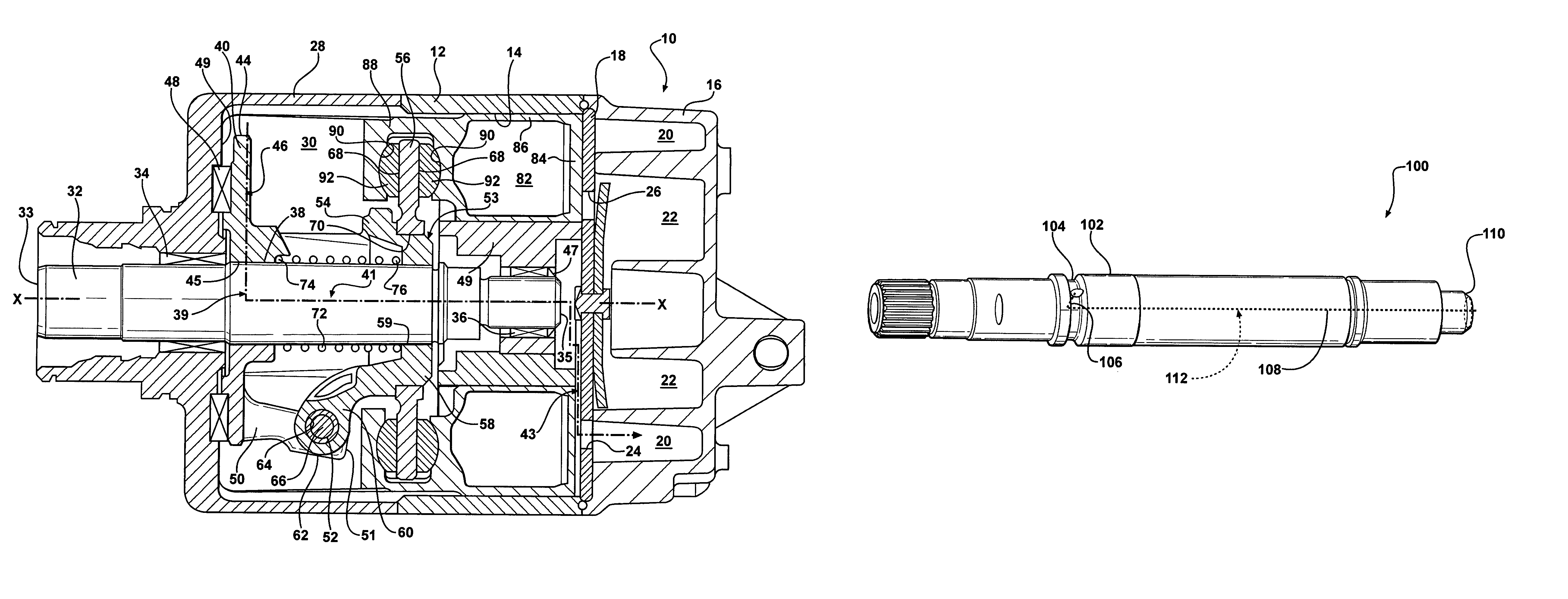
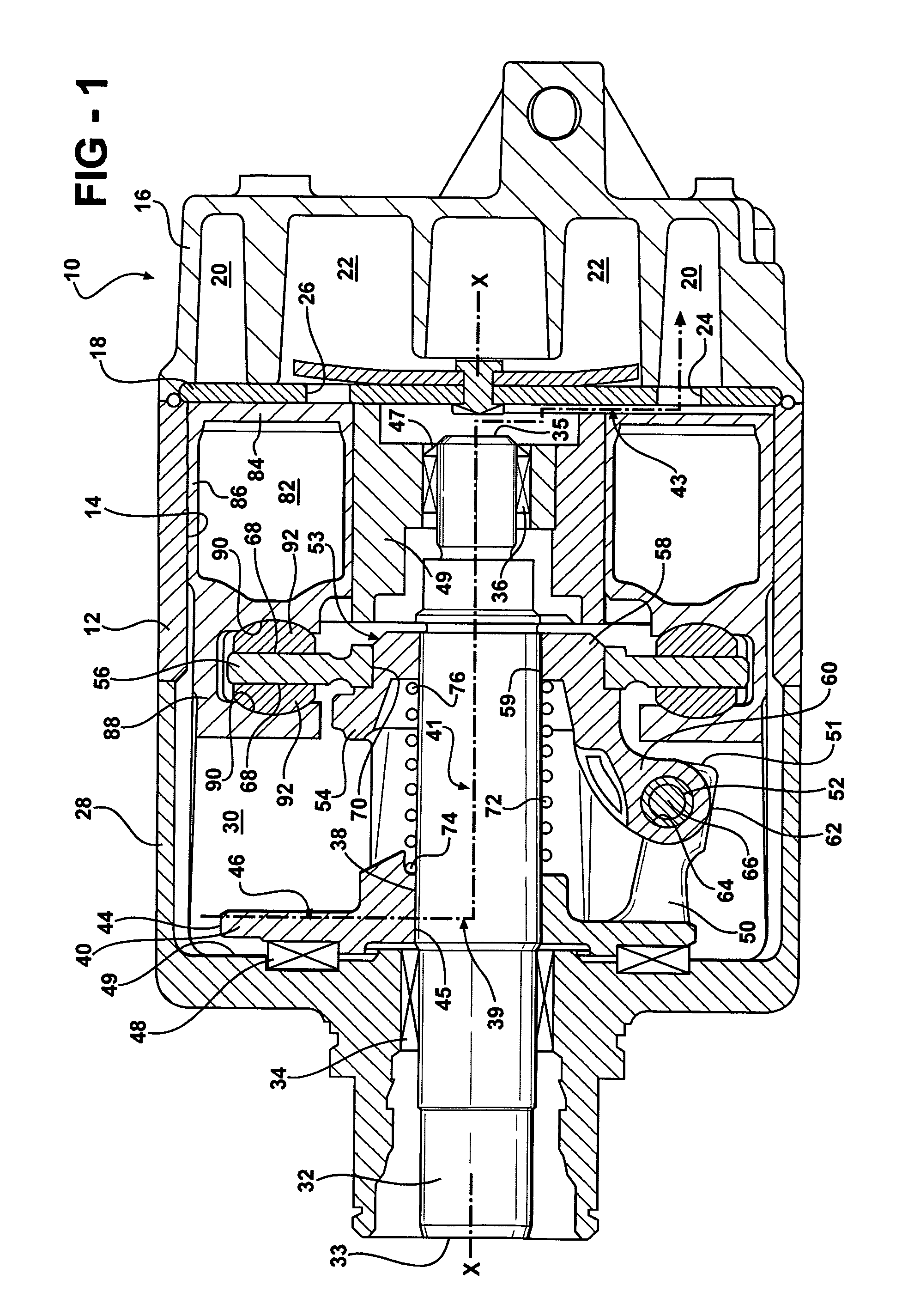
[0016]FIG. 1 shows a variable displacement swash plate-type compressor 10 in accordance with an embodiment of the invention. The compressor 10 includes a cylinder block 12 having a plurality of cylinders 14 formed therein. A head 16 is disposed adjacent one end of the cylinder block 12 and sealingly closes the end of the cylinder block 12. A valve plate 18 is disposed between the cylinder block 12 and the head 16. The head 16 includes a suction chamber 20 and a discharge chamber 22. The suction chamber 20 communicates with th...


PUM


Abstract

An oil separator for a compressor is shown, wherein an oil separating efficiency is maximized and a material cost, a weight, and an assembly time are minimized.

Description

FIELD OF THE INVENTION[0001]The present invention relates to an oil separator and more particularly to an oil separator for a fluid displacement apparatus wherein oil separation capabilities are maximized.BACKGROUND OF THE INVENTION[0002]Compressors used in refrigeration and air conditioning systems such as swashplate type compressors, for example, typically include a lubricating oil mist suspended in a gaseous refrigerant medium. Such compressors also include a first path that provides refrigerant communication between the crank chamber and the discharge chamber, and a second path that provides refrigerant communication between the crank chamber and the suction chamber.[0003]During operation of the compressor, the oil mist lubricates the moving parts of the compressor. However, oil that remains suspended in the refrigerant as it travels throughout the refrigeration circuit can reduce the performance of the refrigeration circuit. Also, by reducing oil available to the moving parts o...

Claims


Application Information

Patent Timeline
Patent Type & Authority Patents(United States)
IPC IPC(8): F01B3/00F01B31/10F04B27/08
CPCF04B27/1054F04B27/109
Inventor THEODORE, JR., MICHAEL GREGORYKELM, BRIANPOY, ALFRED LIMHUANG, YONGBHATIA, KANWAL
Owner HANON SYST
Why Eureka
Try Eureka