Recovery system

a recovery system and drilling fluid technology, applied in the field of drilling fluids, can solve the problems of mud formulations that must be adjusted often, small drilled solids which can accumulate in the drilling fluid, and loss during the drilling process

Inactive Publication Date: 2009-04-21
MI
View PDF13 Cites 29 Cited by
  • Summary
  • Abstract
  • Description
  • Claims
  • Application Information

AI Technical Summary

Problems solved by technology

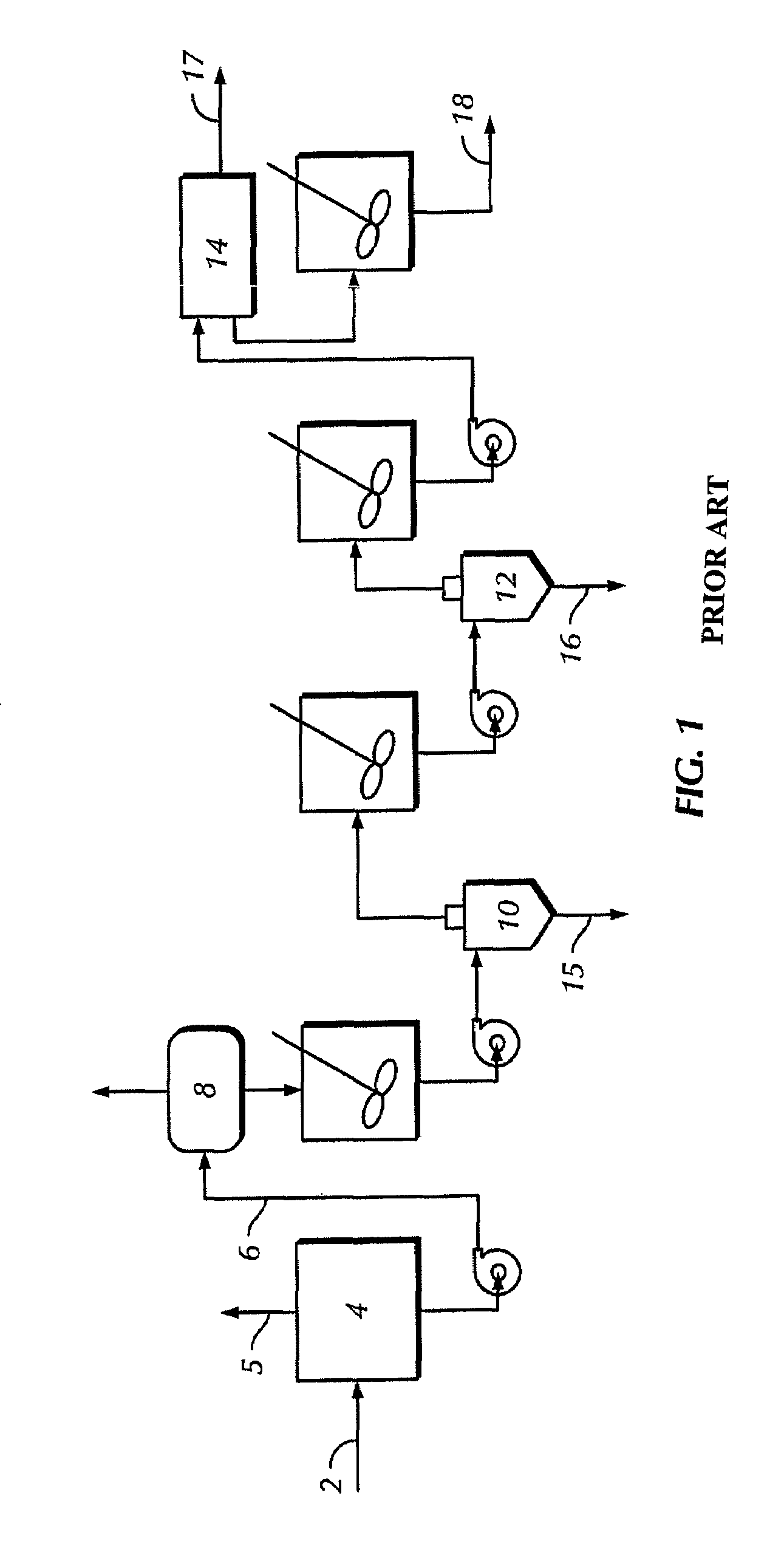
Recycling drilled solids into the wellbore is undesirable, as this can result in smaller sizes of drilled solids which can accumulate in the drilling fluid.
The recovered, clean mud can be recycled, however the mud formulation must often be adjusted due to compounds lost during the drilling process and imperfect separation of drill cutting particles and other drilling fluid additives.
Losses during the drilling process can occur due to the mud forming a filter cake, and thus depositing drill fluid additives on the wall of the wellbore.
While desiring improved wellbore stability, logistics and economics disfavor the use of industrial carbon throughout the entire drilling process.
The amount of industrial carbon thus required can increase the costs of drilling, and can require an excessive amount of storage space on a rig.
Additionally, the drill cuttings and formations encountered during drilling can return particles of similar shape and size to that of industrial carbon, calcium carbonate, and other minerals and additives, and can comminute during circulation through the drill string, each of which can hinder recovery and recycle efforts.

Method used


Image

  • Recovery system
  • Recovery system
  • Recovery system

Examples


examples

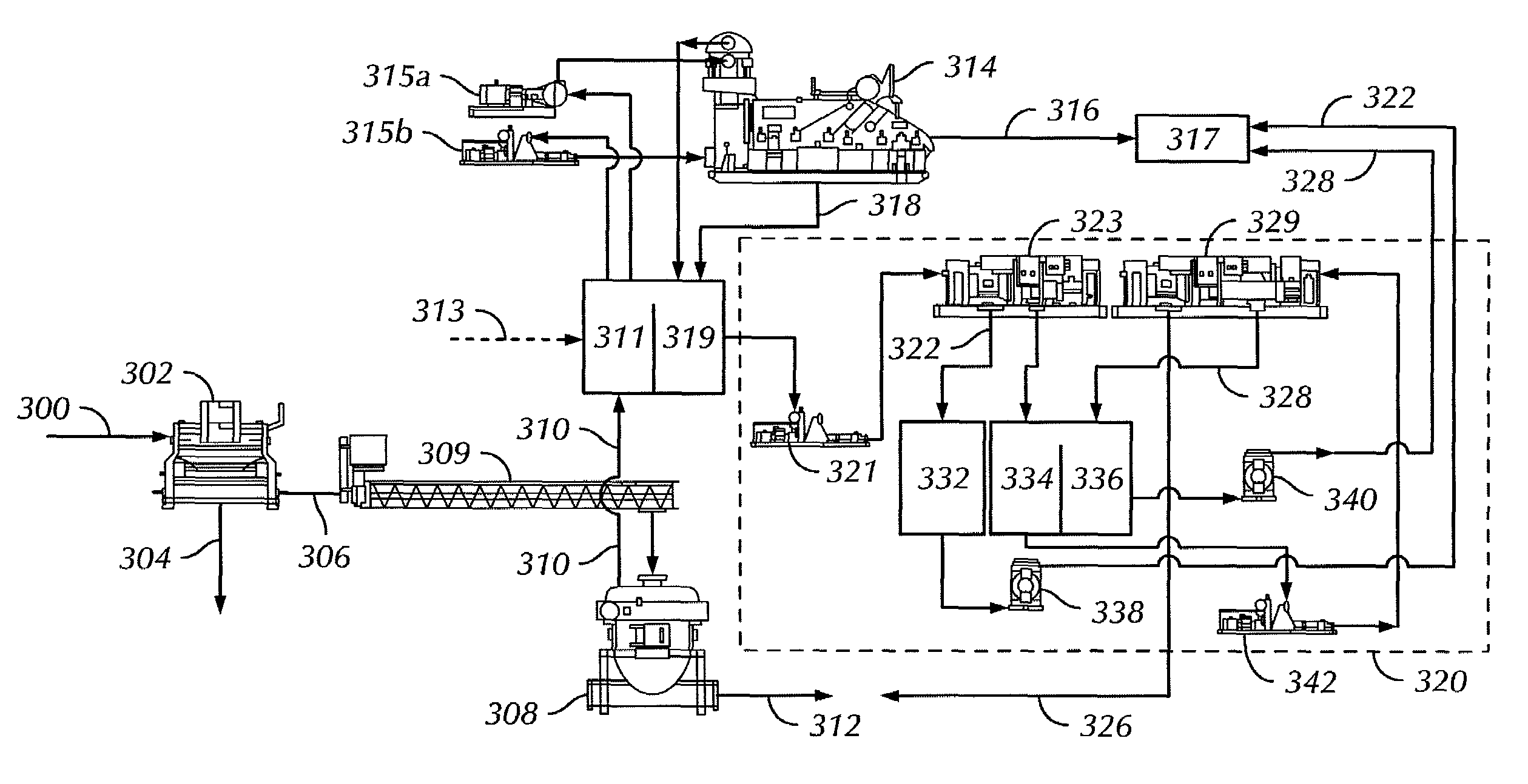
[0088]Samples from two different drilling operations were collected and analyzed to determine where in the process the industrial carbon was being discarded. Although these samples reflect only one or two types of strata encountered during drilling, the analyses of the samples indicate that a size or density separation may be used to sufficiently isolate the industrial carbon for recycle to an active mud system.

[0089]Sample 1: Industrial carbon (G-SEAL®, available from M-I LLC, Houston, Tex.; average particle size of 450 microns, particle diameters ranging from 200-600 microns) was used as an additive in drilling mud during drilling operations. During mud cleaning operations, drilling mud containing drill cuttings and industrial carbon was separated, using shakers having sequentially larger mesh sizes as shown in Table 1. The drilling mud Sample 1 was initially separated in 10 and 40 mesh shakers. The effluent from the 40 mesh shaker was then separated in parallel across screens ran...


PUM


Abstract

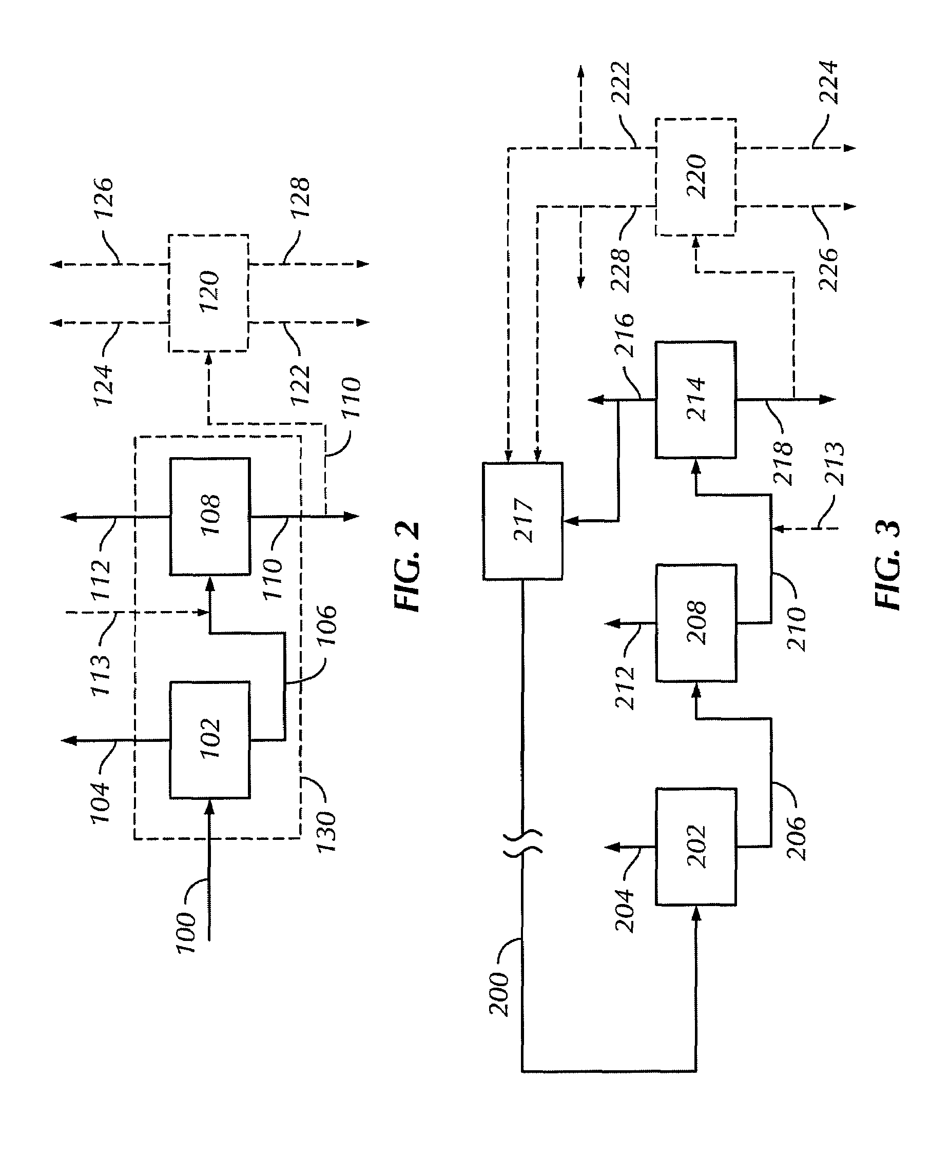
A process for the recovery of drilling fluid additives, including industrial carbon, calcium carbonate, natural and synthetic fibers, and other materials from a mixture. The mixture may include drilling fluids, drilled solids, and drilling fluid additives from a mud system. The process may include: separating at least a portion of the drilled solids from the mixture to form a first effluent and a drilled solids fraction; separating at least a portion of the drilling fluid additives from the first effluent to form a second effluent and a recovered additives fraction; and recycling at least a portion of the recovered additives fraction to the mud system. The drilling fluid additives may have a specific gravity greater than 1.4, and may include particles having an average size greater than 2 microns.

Description

CROSS-REFERENCE TO RELATED APPLICATIONS[0001]This application is a Continuation-in-Part of U.S. patent application Ser. No. 11 / 387,442, filed Mar. 23, 2006.BACKGROUND OF INVENTION[0002]1. Field of the Invention[0003]The invention relates generally to drilling muds, loss circulation materials, industrial materials, and processes to recover the industrial materials for reuse in drilling mud systems.[0004]2. Background Art[0005]When drilling or completing wells in earth formations, various fluids typically are used in the well for a variety of reasons. Common uses for well fluids include: lubrication and cooling of drill bit cutting surfaces while drilling generally or drilling-in (i.e., drilling in a targeted petroliferous formation), transportation of “cuttings” (pieces of formation dislodged by the cutting action of the teeth on a drill bit) to the surface, controlling formation fluid pressure to prevent blowouts, maintaining well stability, suspending solids in the well, minimizing...

Claims


Application Information

Patent Timeline
Patent Type & Authority Patents(United States)
IPC IPC(8): E21B21/06
CPCE21B21/066C02F11/00E21B21/06
Inventor BUTLER, FRANKBROWNING, TIM
Owner MI
Why Eureka
Try Eureka