Automated composting system

a composting system and automatic technology, applied in biomass after-treatment, grain treatment, products, etc., can solve the problems of ineffective and ineffective implementation of most proposed methods and systems, and inability to achieve widespread or even substantial use. , to achieve the effect of facilitating a progressive composting process and reducing the effective heigh

Inactive Publication Date: 2009-04-21
POITRAS BRIAN +1
View PDF26 Cites 41 Cited by
  • Summary
  • Abstract
  • Description
  • Claims
  • Application Information

AI Technical Summary

Benefits of technology

[0024]To facilitate a progressive composting process, the digestion chamber can be subdivided into a plurality of subchambers by at least one divider wall. In such a case, the auger shaft will likely be disposed through each of the plurality of subchambers. First and second divider walls can divide the digestion chamber into primary, secondary, and tertiary subchambers, and first and second intermediate apertures can be disposed in the respective divider walls for enabling a passage of organic material from subchamber to subchamber. To promote a sequential progression of organic material, the input aperture, the first intermediate aperture, the second intermediate aperture, and the exhaust aperture can sequentially decrease in effective height. A temperature sensor and, possibly, a heating element can be operably associated with one or all of the subchambers to enable the subchamber or subchambers to be maintained in a desired temperature condition, such as in the mesophyllic or thermophilic temperature ranges.
[0025]Plural mixing vanes can be retained relative to the auger shaft relative to each subchamber. The plural mixing vanes in each subchamber can have axial portions that cooperate to provide a substantially constant mixing surface, which can have angular spaces between mixing vanes. The mixing surface will preferably be immediately adjacent to an inner wall surface of the digestion chamber over an entire length of the respective subchamber. With this, it can be ensured that all organic material within the subchamber is mixed with each revolution of the auger shaft. One or more vents, each possibly including a fan, can be associated with each of the subchambers for enabling an ingress or egress of gasses relative to the subchamber.

Problems solved by technology

Additionally, it has been found that solid waste decomposition is affected by the size of the particles to be digested.
If, however, ambient temperatures are excessively low or if the compost container is substantially incapable of retaining heat, then achieving suitably elevated temperatures may require the addition of heat or the provision of insulation relative to the compost container.
Unfortunately, however, prior art composting arrangements have suffered from a variety of disadvantages and shortcomings that have caused most proposed methods and systems to be inefficient and unworkable in practice.
As such, most have remained primarily theoretical in nature, never achieving widespread or even substantial usage.
One major issue that has adversely affected the effectiveness and utility of prior art commercial composting systems is a noted inability to achieve full mixing of the retained waste material.
For example, the rudimentary tumbling motion of rotating composters often fails to separate and mix the material to be composted.
Similarly, the mixing blades on the rotating shafts of such composting units by their very nature fail to make widespread contact with the material to be composted.
Such structures are notably inefficient not only with respect to mixing but also in relation to energy consumption.
Just as notably, the need for rotating a large, heavy drum inherently requires complex and heavily built support and rotation arrangements.
Such arrangements are inherently complex in construction and operation.
Furthermore, they are prone to failure and difficult to repair.
Even further, failures in such systems commonly require extended time for repair during which the devices unavailable for composting.
A further shortcoming that has hindered the success of composting systems of the prior art, particularly commercial-type composters, is that malfunctions commonly occur that are unknown to or irremediable by the operator.
For example, much of the operating machinery within the composter, such as any shredder mechanism that might be in use and any rotatable components, is obscured from the operator's view.
Furthermore, most commercial-type composters are designed with a relatively high degree of complexity and expertise but are operated by persons with little or no expertise, which can often be combined with at least some degree of apathy.
As such, an operator might entirely ignore, underestimate, or be completely unaware of a jammed or disabled shredder or other component of the composting system thereby leading to further damage to the system, increased difficulty of repair, and a compromised composting process.

Method used


Image

  • Automated composting system
  • Automated composting system
  • Automated composting system

Examples


Embodiment Construction

[0039]As is the case with many inventions, the present invention for an automated composting system is subject to a wide variety of embodiments. However, to ensure that one skilled in the art will be able to understand and, in appropriate cases, practice the present invention, certain preferred embodiments of the broader invention revealed herein are described below and shown in the accompanying drawing figures.

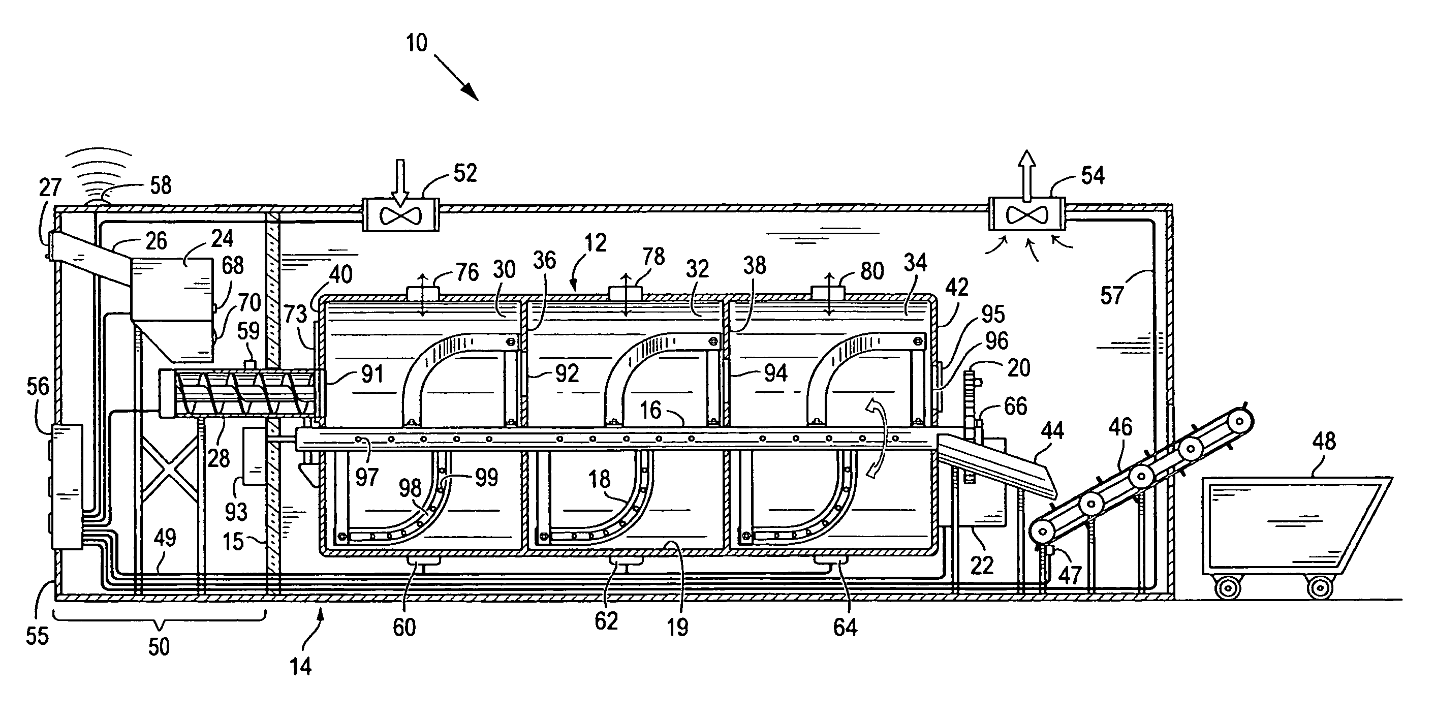
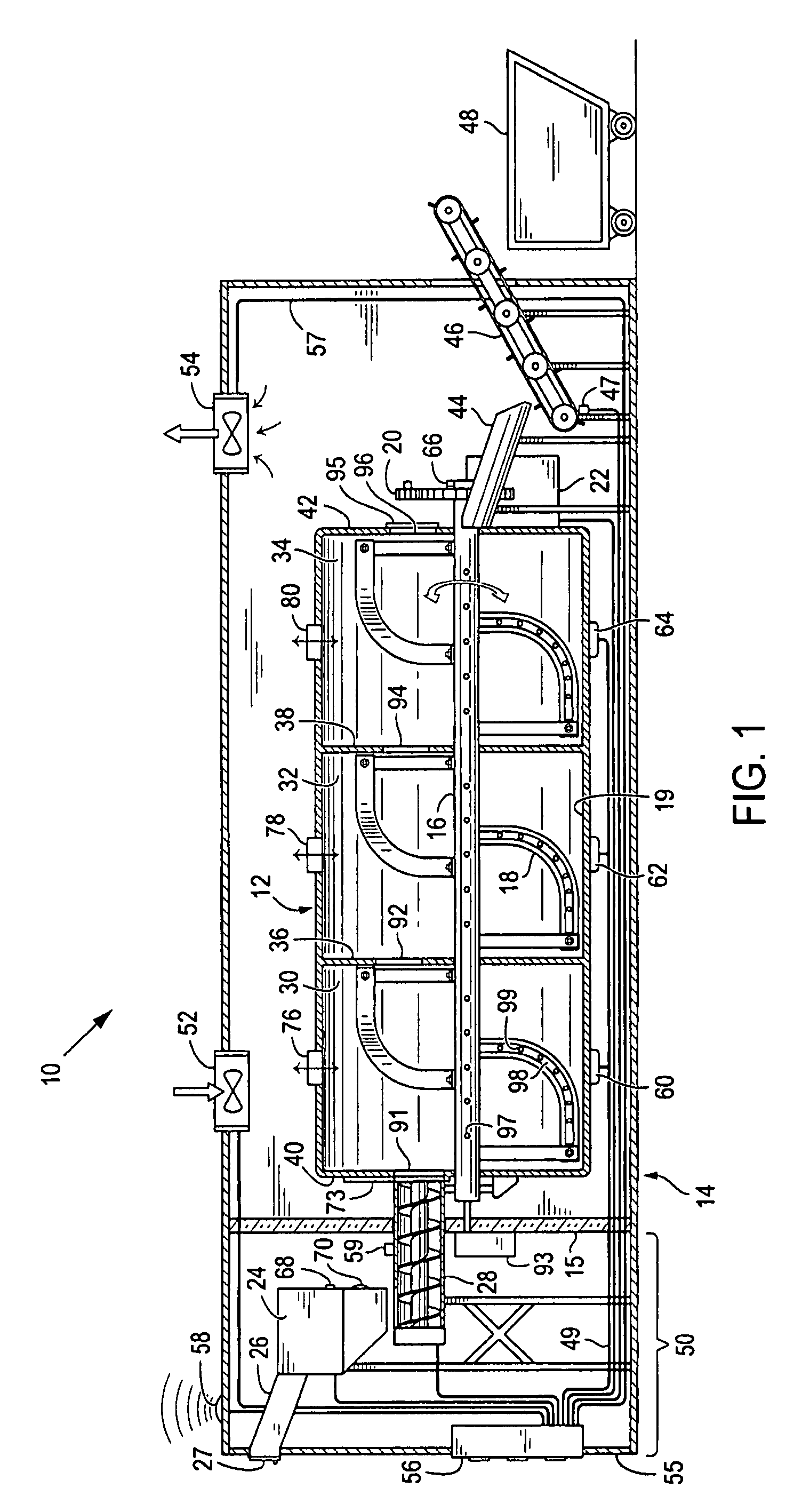
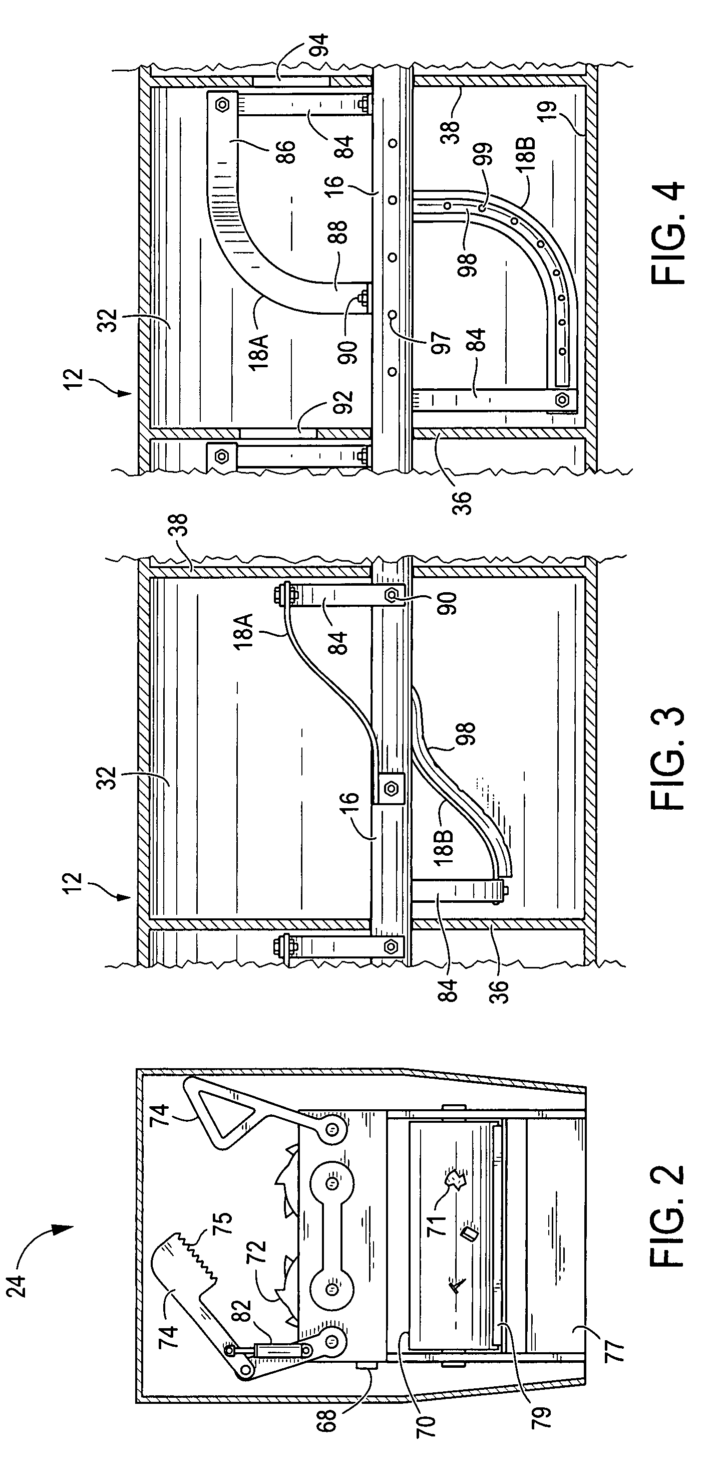
[0040]Looking more particularly to the drawings, a first preferred embodiment of the present invention for an automated composting system is indicated generally at 10 in FIG. 1. There, the composting system 10 is founded on a digestion chamber 12 that is retained in a stationary condition during operation of the composting system 10. In this case, the digestion chamber 12 is disposed within a larger shell housing 14 along with certain other components of the composting system 10 as will be described herein. The digestion chamber 12 and the shell housing 14 certainly could be ...


PUM

PropertyMeasurementUnit
temperaturesaaaaaaaaaa
temperatureaaaaaaaaaa

Abstract

A composting system with a digestion chamber, an auger shaft with at least one mixing vane, and a power unit. The power unit can be hydraulic and can also power a shredding unit and an input conveyor system. A barrier wall can be interposed between those elements and the digestion chamber. The digestion chamber can be divided into subchambers, and sequentially lower apertures can promote a progression of organic material. A malfunction sensor can sense a malfunction of the auger shaft, the shredding unit, or another component. A malfunction report can be provided, including to a remote receiver. The report can include a determined location of the composting system and can be directed to a selected receiver based on the malfunction. Fluids, including gasses and liquids, can be introduced by a supply source in combination with apertures along the auger shaft and/or a mixing vane.

Description

[0001]This application claims the benefit of Provisional Application 60 / 459,172 filed Mar. 31, 2003FIELD OF THE INVENTION[0002]The invention described herein relates generally to composting systems and methods. More particularly, this patent discloses and protects a system and method for automatically composting refuse.BACKGROUND OF THE INVENTION[0003]For a plurality of reasons, the composting of solid waste has proven to be a desirable practice in residential and business applications. During composting, organic matter that would otherwise be added to already overburdened and overflowing landfills is decayed and decomposed into a usable mixture of lower volume and weight that can be reused advantageously in a number of useful endeavors including the fertilization and conditioning of land. As such, composting can be employed to convert materials that would otherwise pose as a nuisance presenting difficulties in handling, transportation, and disposal into a beneficial and potentially...

Claims


Application Information

Patent Timeline
Patent Type & Authority Patents(United States)
IPC IPC(8): C12M1/02
CPCC05F17/0223C05F17/0229C05F17/0276C05F17/929C05F17/936C05F17/986Y02W30/40Y02P20/145
Inventor POITRAS, BRIANMOGLIA, ROBERT F.
Owner POITRAS BRIAN
Why Eureka
Try Eureka