Cerebral spinal fluid shunt evaluation system

a cervical spinal and evaluation system technology, applied in the field of cervical spinal fluid shunt evaluation system, can solve the problems of failure to teach or suggest an apparatus/method for quantifying the flow of fluid through the shunt, unable to achieve the effect of shunt flow,

Active Publication Date: 2009-04-21
NEFF INDIVIDUAL JANINE +1
View PDF173 Cites 7 Cited by
  • Summary
  • Abstract
  • Description
  • Claims
  • Application Information

AI Technical Summary

Problems solved by technology

However, among other things, the apparatus and method disclosed therein fails to teach or suggest an apparatus / method for quantifying the flow of the fluid through the shunt.
However, the apparatus / method disclosed therein suffers from, among other things, variations in thermistor signal due to environmental changes.

Method used


Image

  • Cerebral spinal fluid shunt evaluation system
  • Cerebral spinal fluid shunt evaluation system
  • Cerebral spinal fluid shunt evaluation system

Examples


Embodiment Construction

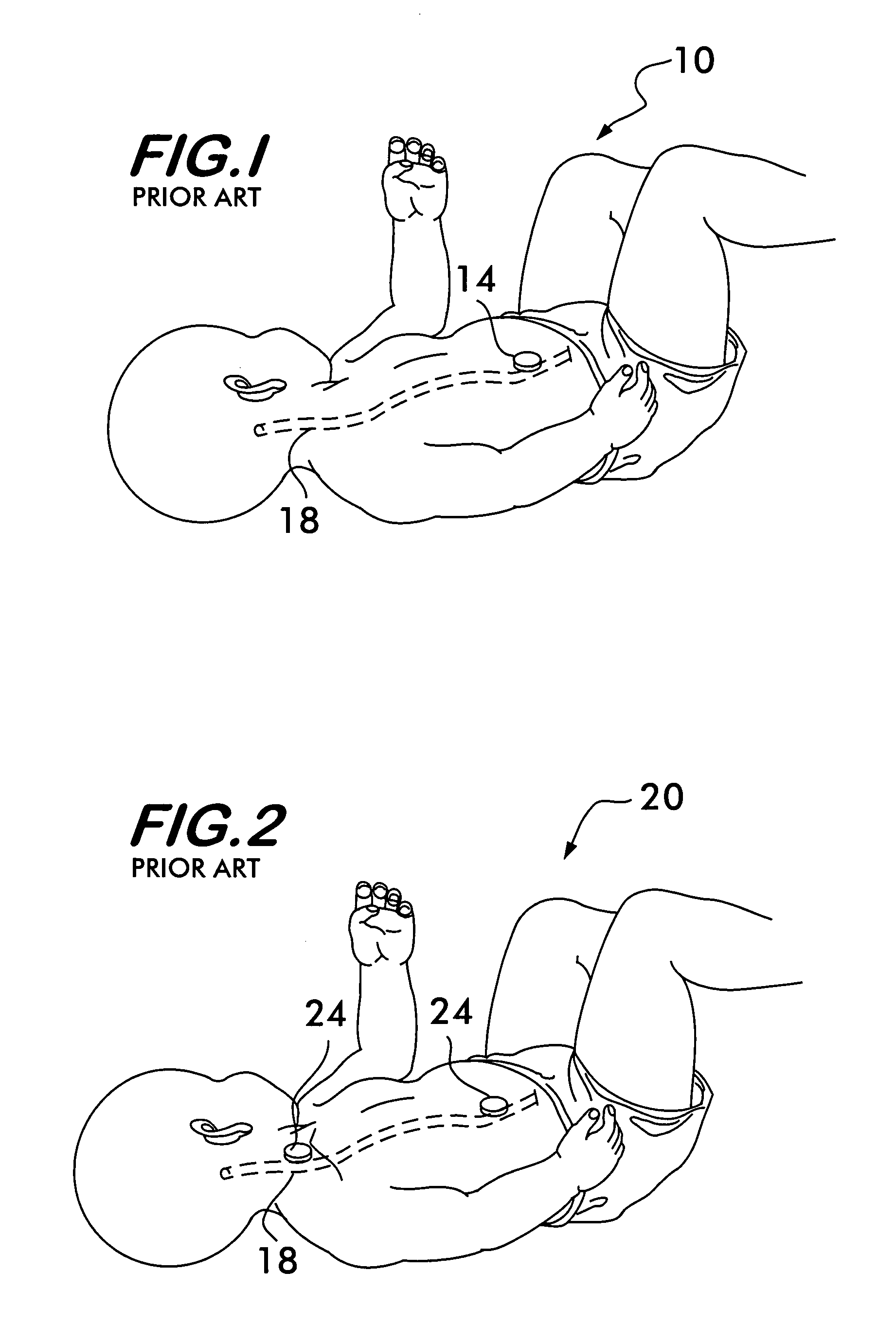
[0026]Referring now to FIG. 1, there is shown a prior art cerebral spinal fluid (CSF) shunt evaluation system 10. The CSF shunt evaluation system 10 includes a shunt tubing 18 that allows CSF to flow from the brain of a patient to another part of the body of the patient such as the abdomen, e.g., for treatment of a patient with hydroencephalus. The CSF shunt evaluation system 10 monitors the flow of the CSF through the shunt tubing 18 by means of upstream cooling of the CSF and a downstream sensor 14. The sensor 14 can be a temperature sensor, such as a thermistor, a thermocouple or a semiconductor sensor. The downstream sensor 14 is disposed over the shunt tubing 18 in the vicinity where the shunt tubing 18 empties into the abdominal cavity in order to detect changes in temperature as the cooled CSF is transported from the cooled region to the abdominal cavity.

[0027]The sensor 14 could be conventional temperature sensitive device wherein the internal resistance of the sensor 14 var...


PUM


Abstract

A method for evaluating cerebrospinal fluid (CSF) flow rate in a CSF shunt applied to a patient for transmitting the CSF between first and second locations of the patient includes applying temperature sensors to the CSF shunt for determining a flow rate of the CSF through the shunt to provide a determined CSF flow rate and applying an error correction sensor to the patient for providing an error correction signal. The determined CSF flow rate is adjusted in accordance with the error correction signal to provide a corrected CSF flow rate. The sensor can be a temperature sensor such as a thermistor. The CSF is cooled and a temperature value of the CSF is measured in accordance with the cooling. A time value is determined in accordance with the temperature value and the CSF flow rate is determined in accordance with the time value.

Description

BACKGROUND OF THE INVENTION[0001]1. Field of Invention[0002]This invention relates to cerebrospinal fluid shunts and, more particularly, to apparatus and methods for quantitatively detecting the flow of cerebrospinal fluid in such shunts noninvasively.[0003]2. Description of Related Art[0004]A cerebrospinal fluid (CSF)shunt includes a system of tubing that allows CSF to flow from a patient's brain to another part of the body (e.g., abdomen to relieve pressure in the spinal column). As a result, it is desirable to know, periodically, that the pathway of the CSF shunt remains unobstructed to permit CSF flow and what the flow rate is. It is also desirable to make these determinations non-invasively when quantifying the CSF flow.[0005]The following describe different apparatus and methodologies that have been used to monitor, determine or treat body fluid flow, including CSF flow through a shunt.[0006]“A Thermosensitive Device for the Evaluation of the Patency of Ventriculo-atrial Shunt...

Claims


Application Information

Patent Timeline
Patent Type & Authority Patents(United States)
IPC IPC(8): A61B5/00A61M3/00A61M37/00A61M27/00
CPCA61M27/006A61M2205/3379
Inventor NEFF, SAMUEL
Owner NEFF INDIVIDUAL JANINE
Why Eureka
Try Eureka