Transmission power optimization apparatus and method

a technology of transmission power and optimization apparatus, applied in the field of optical communication, can solve the problems of link budge, degrade the osnr of a wavelength, and incur different amounts of noise, and achieve the effects of low cost, low cost, and reduced power deviation of received signals

Active Publication Date: 2009-04-21
CIENA
View PDF6 Cites 68 Cited by
  • Summary
  • Abstract
  • Description
  • Claims
  • Application Information

AI Technical Summary

Benefits of technology

[0009]With such an arrangement, a low cost system is provided that is capable of controlling transmit power to achieve a desired OSNR at a receive endpoint. The system utilizes the fact that the aggregate power for a plurality of channels can be controlled in the network, and uses this characteristic to trade transmission power of signals having a high OSNR at a receive point for those signals having a low OSNR at the end point. With such an arrangement, the power deviations of received signals may be reduced by coarse adjustment of transmit signals. Because only coarse adjustment of the transmit power of the lasers is needed, the present invention may use a low cost direct modulated laser (DML), which can be calibrated to many power different power levels of coarser granularity. Such a system removes the need for electronic Variable Optical Attenuators (eVOAs) on each channel, for finer calibration of transmit signals, which are expensive. In systems where eVOAs and VOAs are used, the present invention allows eVOAs and VOAs to be moved to a location in the transmission path where they adjust aggregate power on a plurality of wavelengths, rather than individual wavelengths, making them more cost effective on networks with higher wavelength counts.

Problems solved by technology

However, as wavelengths pass through different components from a transmitter to a receiver, gain or loss of power (due to ripple) causes wavelengths to incur different amounts of noise, because the wavelength gains or loses power as it traverses amplifiers in its path.
In particular, amplifiers, which are often needed to boost signal power during transmission, also amplify the noise of a signal and introduce new noise, and therefore degrade the OSNR of a wavelength.
However, the addition of components can rapidly cause the link budge to be exceeded.
One problem with such an arrangement, however, is that signal regeneration is expensive, and thus it is desirable to minimize the number of signal regenerators in a transmission path.
However, introduction of power balancing in such a solution is often not desirable in metro networks, because introducing overhead into a link solely to assist in power balancing, but otherwise providing no functional value, undesirably increases the cost of a cost-sensitive system.

Method used


Image

  • Transmission power optimization apparatus and method
  • Transmission power optimization apparatus and method
  • Transmission power optimization apparatus and method

Examples


Embodiment Construction

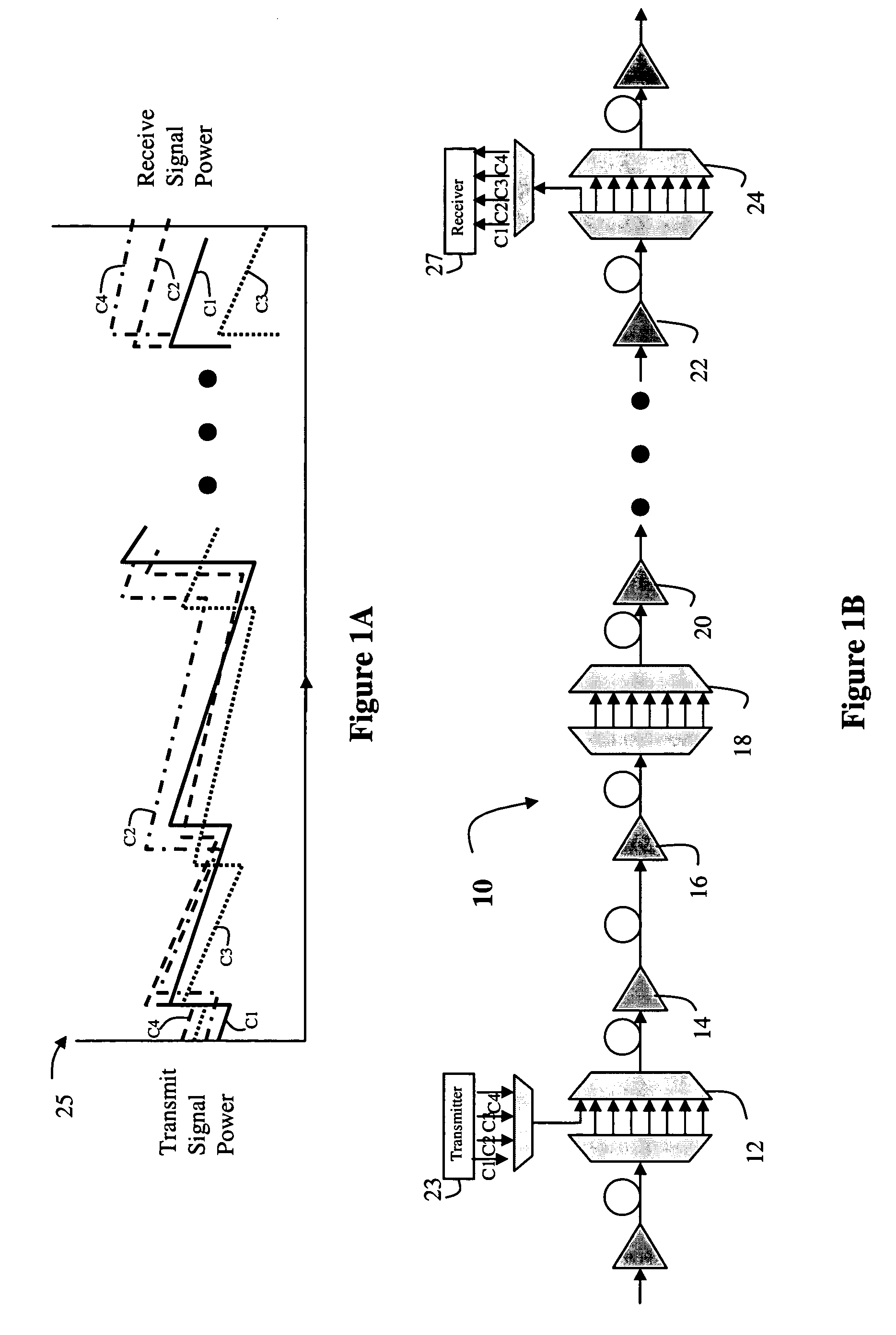
[0015]Referring now to FIG. 1, a number of links are shown in an optical network 10. In one embodiment of the invention, the optical network is a Dense Wavelength Division Multiplex (DWDM) system, which combines and transmits multiple signals simultaneously at different wavelengths (or channels) on the same fiber, effectively transforming one fiber into multiple virtual fibers. However, as will become more apparent below, the present invention may be used in other optical networks, such as WDM networks etc., and the present invention is not limited to any particular type of optical network.

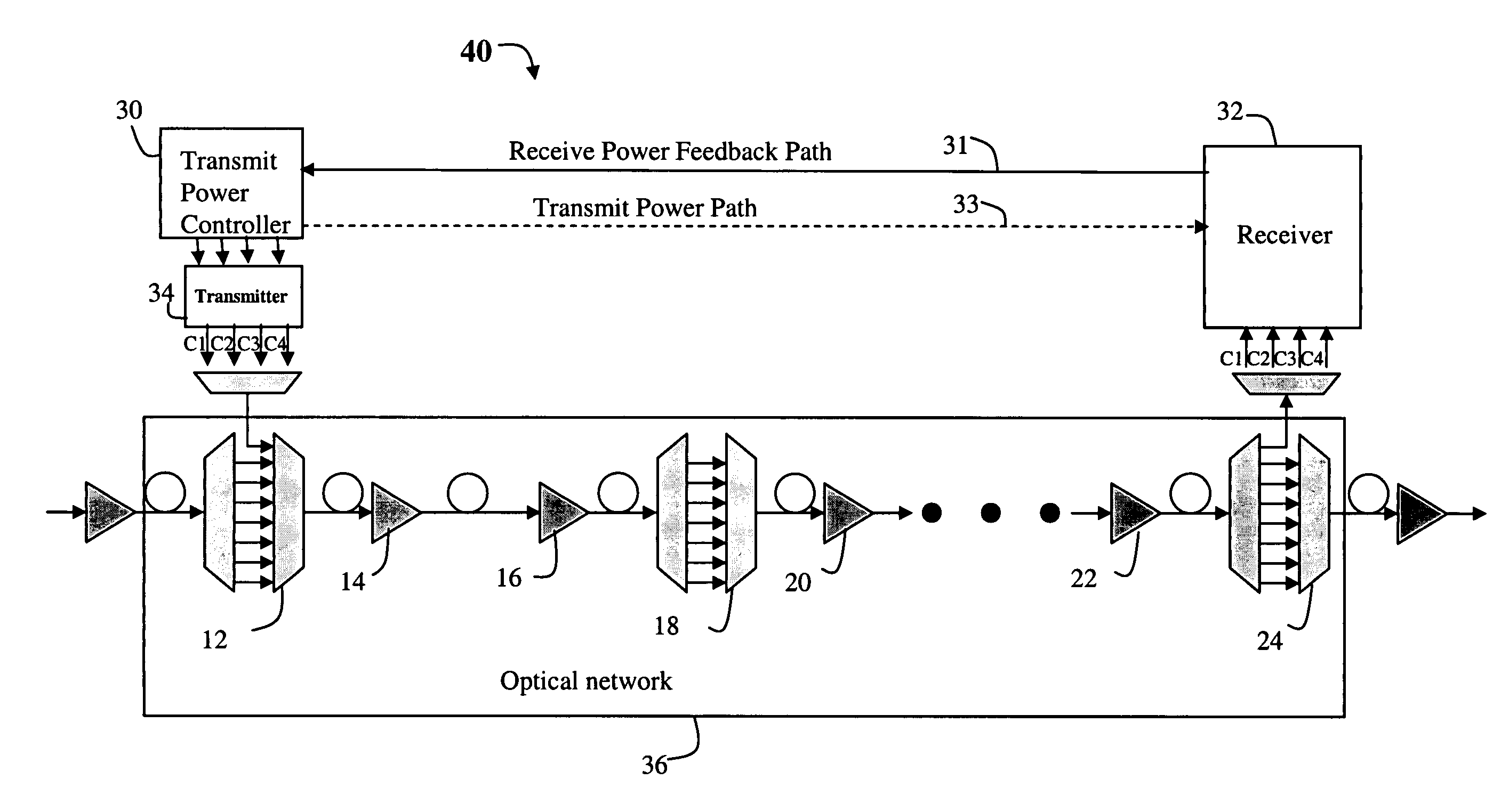
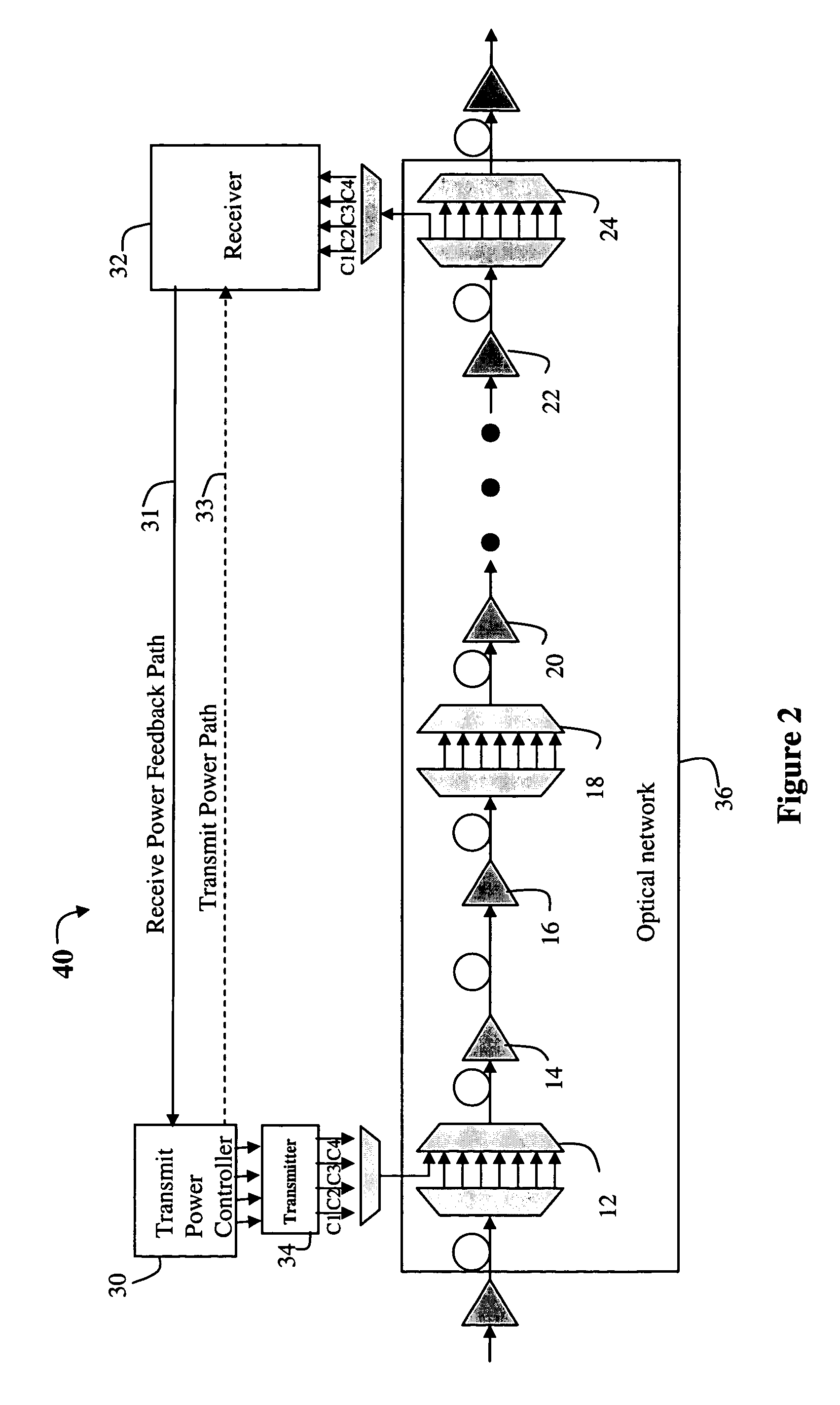
[0016]In general, the optical transport path includes a series of optical add drop multiplexers (OADMs) 12, 18 and 24 and other components such as amplifiers 14, 16, 20 and 22, or filters and the like. At various points in the optical path, the OADM is used to add new signals onto a given fiber. This feature is illustrated in FIG. 1B, where signals on channels C1, C2, C3 and C4 are transmitted for...


PUM


Abstract

A method and system is provided that is capable of controlling transmit power to achieve a desired OSNR at a receive endpoint. The system utilizes the fact that the aggregate power for a plurality of channels is controllable between a transmission point and a receive point in the network, and uses this characteristic to coarsely adjust transmission powers in the network to achieve desired OSNR results.

Description

FIELD OF THE INVENTION[0001]This invention relates generally to the field of optical communication and more specifically to a method and apparatus for optimizing power transmission in an optical network.BACKGROUND OF THE INVENTION[0002]Fiber optic technology uses glass or plastic threads, called ‘fibers’ to transmit data. A fiber optic cable consists of a bundle of fibers, each of which is capable of transmitting messages modulated onto light waves. Dense Wavelength Division Multiplexing (DWDM) is an optical technology that works by combining and transmitting multiple signals simultaneously at different wavelengths (or channels) on the same fiber. In effect, one fiber is transformed into multiple virtual fibers.[0003]DWDM networks strive to deliver each signal to a receiver with a satisfactory Optical Signal to Noise Ratio (OSNR) to achieve the desired system Bit Error Ratio (BER). Thus, the noise incurred by a signal as it traverses the network from transmitter should not exceed a ...

Claims


Application Information

Patent Timeline
Patent Type & Authority Patents(United States)
IPC IPC(8): H04B10/04
CPCH04B10/07955H04J14/0221
Inventor LEWIS, STEPHENBRAGG, NIGEL
Owner CIENA
Why Eureka
Try Eureka