Caliper for a disk brake

a disc brake and caliper technology, applied in the direction of sliding contact bearings, engine components, mechanical equipment, etc., can solve the problems of reducing increasing wear, and affecting the stability of the cartridge, so as to reduce the stress level and avoid the effect of tension peaks and loss of inner stability

Inactive Publication Date: 2009-04-28
CONTINENTAL TEVES AG & CO OHG
View PDF16 Cites 8 Cited by
  • Summary
  • Abstract
  • Description
  • Claims
  • Application Information

AI Technical Summary

Benefits of technology

[0010]It has shown that tension peaks can be avoided because the teeth of the toothing are provided uniformly and circumferentially on an end portion in order to form a star-like cross-section. The uniform, star-like geometry of the supporting teeth causes the circumferential forces to be distributed evenly onto all teeth, the stress level being minimized as a result.
[0011]The above-mentioned advantage of the uniform component stress is also achieved for the accommodations means, when the form-fit accommodation means have a negative profile with respect to the star-like cross-section of the end portion. In a particularly advantageous embodiment of the invention, the accommodation means are configured integrally in a cartridge of the readjusting device. Configuring the cartridge as a star-like accommodation reinforces it, instead of losing inner stability on account of the supporting slots as is the case in the state of the art. This allows reducing the wall thickness of the cartridge and likewise obviates the need for a separate manufacturing process to make the slots.
[0013]It is, however, also feasible to manage without the use of a cartridge and to design the accommodation means integrally in a portion of the bore. This allows further reducing the number of components by realizing the tangential support directly by way of a suitable internal profile in the bore of the housing.
[0015]According to an independent solution to the problem, a calotte arrangement is provided as an axial bearing, which comprises a calotte shell with a concavely curved surface and a calotte pivot with a convexly curved surface. This bearing concept is favorable in that the contact surface in the bearing is very small, with the result that friction is considerably diminished. This reduces the torque transmitted into the readjusting device, which results in a decrease of the forces developing in spindle and cartridge, and no excessive surface pressures and tension peaks develop therein. A favorable shaping of the surfaces implies that they are spherical.
[0018]When the calotte shell and an end portion of the spindle have an integral design, when the calotte shell is provided on an axial front surface of the end portion of the spindle, and the calotte pivot is integrally designed with an end portion of the shaft, the costs of manufacture and assembly will be considerably diminished because the manufacture of the components is simplified and their number is reduced.

Problems solved by technology

It is disadvantageous in this respect that considerable surface pressures and tension peaks occur at the edges of the slots and at the projections of the spindle, and that this uneven component stress leads to an increase in wear.
The longitudinal slots cause low stability of the cartridge, thus necessitating a major wall thickness of the cartridge.
Since rolling bearings are cost-intensive, increase the complexity of components and require hardening of the respective sliding surfaces, this solution entails high costs of manufacture and is, therefore, considered not practicable.
Compared thereto, a slide bearing with an axially active slide bearing plate brings about cost benefit, yet causes increased component tension in the readjusting device due to the higher bearing friction.

Method used


Image

  • Caliper for a disk brake
  • Caliper for a disk brake
  • Caliper for a disk brake

Examples


Embodiment Construction

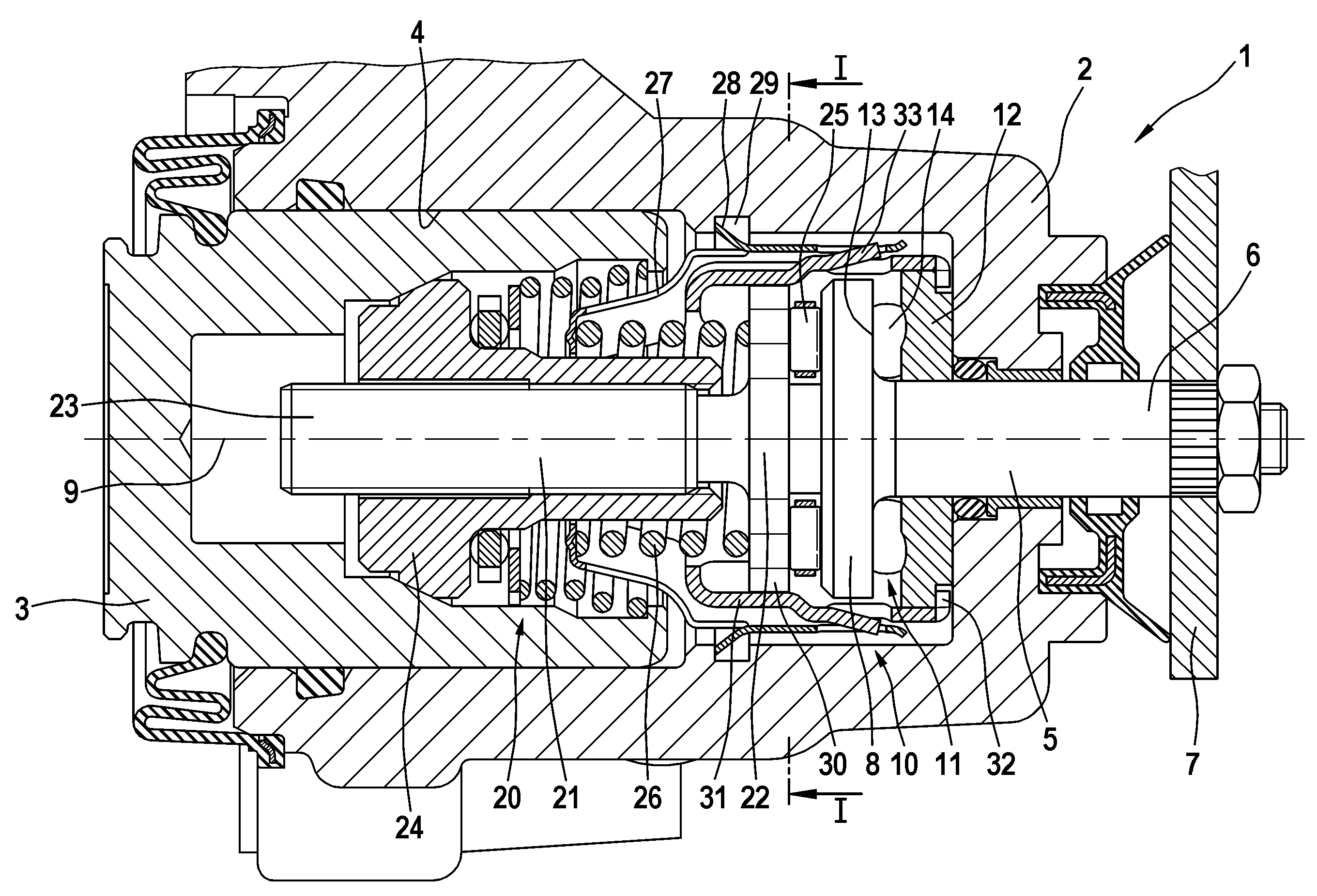
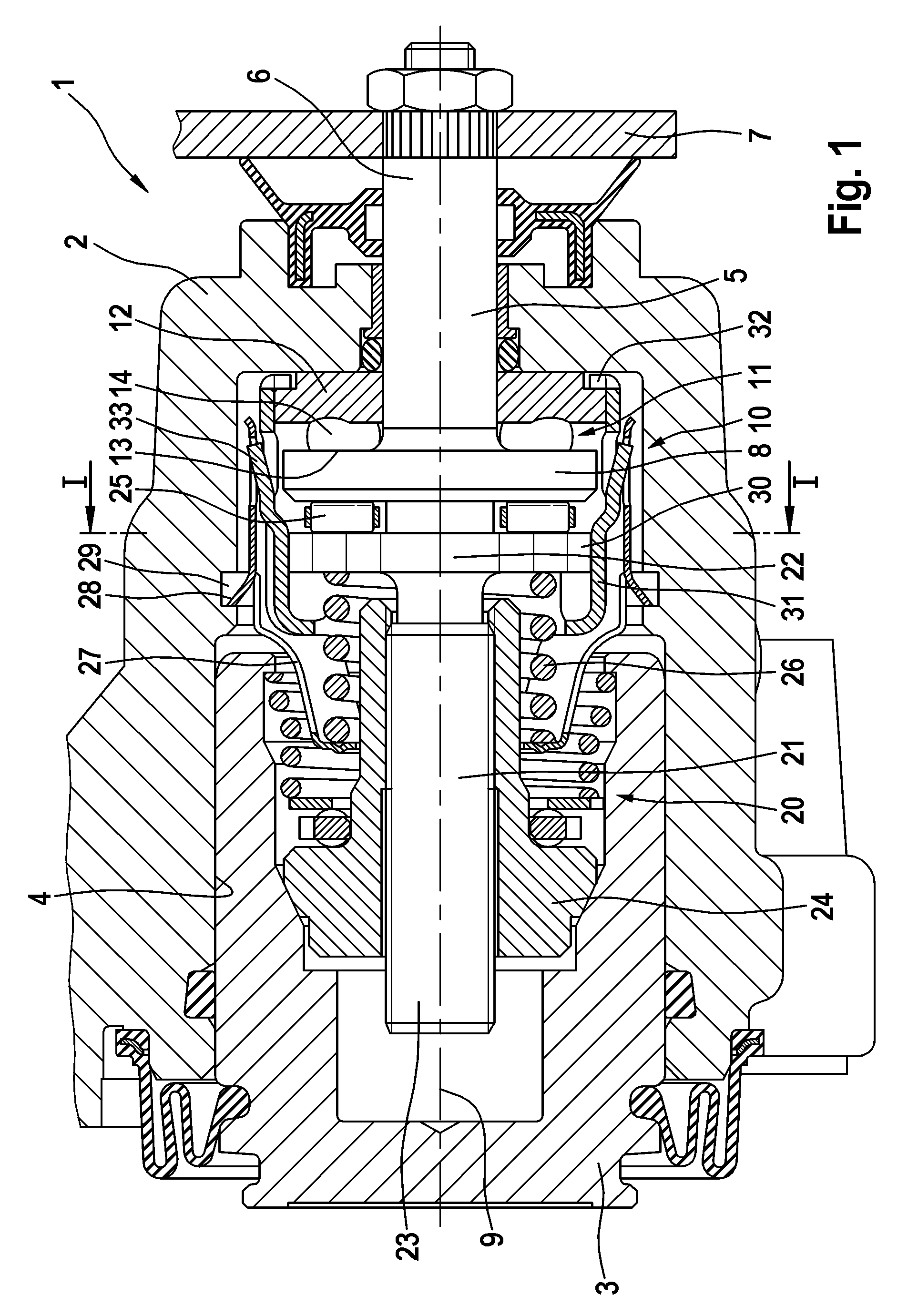
[0029]The brake caliper 1 of a motor vehicle disc brake illustrated in FIG. 1 comprises, among others, a housing 2, and a piston 3 that is displaceably arranged in a bore 4 for brake application. Piston 3 can be displaced by means of hydraulic pressurization in the case of a service brake operation. To realize a parking brake operation, a shaft 5 is provided, which permits displacing the piston 3 by way of an actuating device 10 inside bore 4. Shaft 5 extends with a shaft end 6, at which an operating lever 7 is fitted, through an opening in housing 2. The actuating device 10 acts upon piston 3 by the intermediary of a length-variable readjusting device 20.

[0030]The actuating device 10 comprises a ramp arrangement 11, which includes a ramp element 12 formed fast with the housing and a ramp element 13 being rotatable relative thereto. The ramp element 13 is designed integrally with a disc-shaped end portion 8 of shaft 5. Several roll bodies 14 are interposed between the ramp elements ...


PUM


Abstract

A brake caliper of a disc brake includes a housing with a bore, in which a piston is arranged in an axially displaceable fashion, a shaft for actuation, which is mounted in a rotatable and axially displaceable fashion, two ramp elements being rotatable in relation to each other, a readjusting device with a spindle, and an axial bearing that is active between the shaft and the spindle. A generic brake caliper of a disc brake includes components having a construction to withstand stress so that they are exposed to even, low stress without detrimental tension peaks. A toothing is provided on a circumference of the spindle, and a form-fit accommodation means for the toothing is provided. The accommodation means are unrotatably connected to the housing and secure the spindle against twisting. A calotte arrangement is also provided as an axial bearing, which comprises a calotte shell with a concavely curved surface and a calotte pivot with a convexly curved surface.

Description

RELATED APPLICATIONS[0001]This application is the U.S. national phase application of PCT International Application No. PCT / EP2005 / 056221, filed Nov. 25, 2005, which claims priority to German Patent Application No. DE102004057276.3, filed Nov. 26, 2004 and German Patent Application No. DE102005056166.7, filed Nov. 23, 2005, the contents of such applications being incorporated by reference herein.FIELD OF THE INVENTION[0002]The present invention relates generally to brake calipers, and in particular to a brake caliper with components constructed so that the caliper is subject to an even, low stress without detrimental stress peaks.BACKGROUND OF THE INVENTION[0003]EP 0 403 635 B1 discloses a combined brake caliper of this type for use in a motor vehicle disc brake. The brake caliper comprises a housing with a bore, in which a piston is arranged in a displaceable fashion for brake application. A shaft is pivoted in the brake housing for parking brake operations, and the shaft extends th...

Claims


Application Information

Patent Timeline
Patent Type & Authority Patents(United States)
IPC IPC(8): F16D65/56
CPCF16C17/08F16D65/18F16D65/567F16D2055/0062F16D2121/02F16D2121/14F16D2123/00F16D2125/36F16C2361/45F16D65/14F16D65/56
Inventor PETRI, RALPHWEILER, ROLFBALZ, JURGENWEIDENWEBER, MICHAEL
Owner CONTINENTAL TEVES AG & CO OHG
Why Eureka
Try Eureka