Member-joining device

a member and jointing technology, applied in the direction of rod connections, fastening means, dowels, etc., can solve the problems of inability to fasten over strength in the direction of wall thickness, more or less a backlash in the joining status, and difficulty in ensuring the firmness of each member

Inactive Publication Date: 2009-04-28
KOKUYO CO LTD
View PDF22 Cites 9 Cited by
  • Summary
  • Abstract
  • Description
  • Claims
  • Application Information

AI Technical Summary

Benefits of technology

[0007]The present invention relates to providing a member-joining device which allows each end face of pipe members to be securely and coherently joined with sufficient fastening force and without backlash according to necessity when such as pipe members are fixed to each other even if its wall thickness is thin.
[0009]Thus when the first member and the second member are drawn with the drawing means, the force acts along the face direction of opposing walls through the first bridge member and the second bridge member. Accordingly, the drawing force with the drawing means does not act to cave the wall in the direction of thickness and the members can be pressed and fixed to each other even if the first and second member are made of a thin material in comparison with the traditional joining means. Wherein, each opposing wall is not limited to be in parallel and for instance may include facing walls of such as a round pipe. Further the drawing force becomes a pressing force and therefore the factor which may cause a backlash can be eliminated because the drawing force acts along the face board direction of opposing walls and the members are pressed and joined to each other by such force.
[0011]Accordingly, the first member and the second member are closely contacted to each other by the drawing force, a fractional force in the sliding direction along the contact face between the first member and the second member is generated, and then the position determining means restricts the sliding movement at the predetermined position and the position determination action of the first member and the second member can be securely carried out. Thus, the first member and the second member can be securely coherently joined at the predetermined position. Further, the screw hole can be set as longer by installing the first fixing portion to the projection portion because the projection portion of the position determining means can be thicker. Therefore the drawing force of the drawing means according to the screwing of the screw can be more secured.
[0012]Further, the first member and the second member can have a displacement prevention means corresponding to the force at almost right angles to the sliding force, and the displacement prevention means can control the displacement action at almost right angles to the sliding force, and the position determination action of the first member and the second member can be securely carried out. Thus, the first member and the second member can be securely coherently joined at the predetermined position.
[0014]To be able to determine the position at right angles direction in the longitudinal direction in the connection of the first member and the second member, the second member is a pipe member; the first member comprises a pipe-like outer member having a coinciding cross section outline form with the second member and an inner member projecting away from each end face of the outer member; wherein each end face of the outer member is the contact face; and preferably the first member and the second member are joining by inserting the projecting portion to the end face of the second member. Accordingly, the inner member performs as the position determining means and the displacement preventing means and the contact face and the end face of both members can be joined securely without a gap.
[0017]The line with like / \ shape in the side view is preferably set in the lower half portion of up-and-down direction of the first member and the second member in order to effectively prevent opening the betweenness of the first member and the second member underside of the connection boundary region due to their own weight or uploaded weight.

Problems solved by technology

However, when each separated wall is fastened as disclosed in the former instance, it is different from the case when each coherent wall is fastened, and it cannot be fastened over strength in the direction of wall thickness because the fastening force acts to cave the wall in the thickness direction.
Therefore when the thickness of the wall is thin, secured firming of each member may be difficult because sufficient fastening force cannot be obtained.
Further there may be more or less a backlash in the joining status due to a difference between the screw hole and the screw and a process deviation of the screw hole.
On the other hand, in the latter instance, in addition to the same defect as more or less backlash in the joining status, according to this status, a defect may take place that a favorable joining status in which each end face of hollow member is joined face to face cannot be obtained (specifically there is an unexpected gap between the joining portion of each end face).

Method used


Image

  • Member-joining device
  • Member-joining device
  • Member-joining device

Examples


Embodiment Construction

[0040]The inventors describe the implementation of the present invention referring to figures.

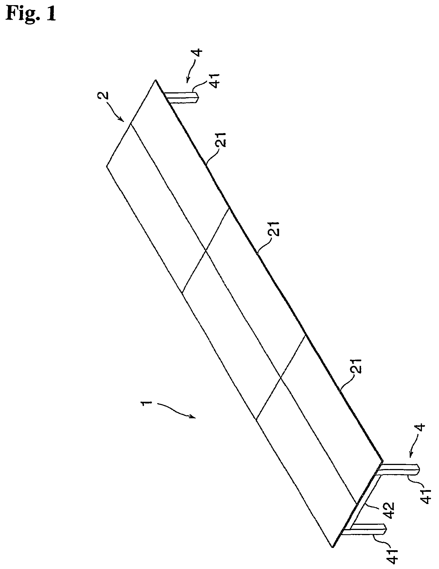
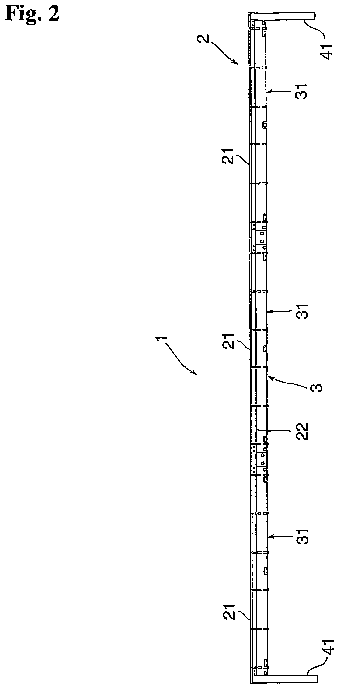
[0041]A member-joining device relating to an implementation of the invention is applied to tables illustrated in such as FIG. 1. Table 1 comprises top board 2, main frame 3 mainly supporting top board 2, and leg 4 supporting main frame 3 at its both ends.

[0042]Referring to FIG. 1, FIG. 2 and FIG. 3, top board 2 is formed by attaching a pair of top board element 21 having a rectangular shape in the depth direction and setting plural elements board to board along the longitudinal direction of top board element 21. Side frame 22 and supporting frame 23 are installed to each top board element 21 to increase strength. Side frame 22 installed in the inside within a certain distance from longer side of board element 21 and along one of longer sides of board element 21 is a square shape pipe. Plural supporting frame 23 (3 frames according to the embodiment of the invention) are installed between ea...


PUM


Abstract

A member-joining device with which, when pipe members etc. are fixed to each other, a sufficient fastening force can be obtained even if the members have thin wall thickness. Member-joining device 8 has a first bridge member, a second bridge member and drawing means 6. First bridge member 81 joins first member 5 having a pair of opposing walls 53, 53 and a second member 31 having a pair of opposing walls 311, 311 and is spanned at a predetermined position of the first member between the opposing walls 53, 53. Second bridge member 82 is spanned at a predetermined position of second member 31 between the opposing walls 311, 311. Drawing means 6 draws first bridge member 81 and second bridge member 82 in the direction where both members are closer to each other. Accordingly, first member 5 and second member 31 are pressed and joined to each other by a drawing force of drawing means 6.

Description

CROSS REFERENCE TO PRIOR APPLICATION[0001]This is a U.S. National Phase Application under 35 U.S.C. §371 of International Patent Application No. PCT / JP2004 / 007158, filed May 19, 2004, and claims the benefit of Japanese Patent Application No. 2003-160043, filed Jun. 4, 2003 both of which are incorporated by reference herein. The International Application was published in Japanese on Dec. 16, 2004 as WO 2004 / 109129 A1 under PCT Article 21(2).TECHNICAL FIELD[0002]The present invention relates to a member-joining device which is used to join each member having a pair of opposing walls of such as pipe members and channel members.BACKGROUND ART[0003]Traditionally, for instance, when each hollow member such as a pipe member is fastened by such as a screw, each separated outer wall of the hollow members overlapped with a different outer size is fastened as disclosed in Japanese Laid Open Patent Publication H5-146316.[0004]Or when the outer sizes of each hollow member are the same, an inner ...

Claims


Application Information

Patent Timeline
Patent Type & Authority Patents(United States)
IPC IPC(8): F16B7/00F16B12/36F16B13/00F16B7/18
CPCF16B7/18Y10T403/7079Y10T403/7081Y10T403/7084Y10T403/55Y10T403/7077
Inventor ZENDA, YOUICHIMATSUZAKI, KATSUYA
Owner KOKUYO CO LTD
Why Eureka
Try Eureka