Power-enabled connector assembly with heat dissipation apparatus and method of manufacturing

a technology of power-enabled connectors and heat dissipation apparatus, which is applied in the direction of network connectors, two-part coupling devices, and coupling device connections, etc., can solve the problems of formidable practical limitations, no foregoing solutions appear to contemplate the active capability of devices, and the small physical constraints of jacks or connectors, etc., to achieve the effect of adding power handling (and heat dissipation) capability

Inactive Publication Date: 2009-04-28
PULSE ELECTRONICS
View PDF43 Cites 69 Cited by
  • Summary
  • Abstract
  • Description
  • Claims
  • Application Information

AI Technical Summary

Benefits of technology

[0037]In a fifth aspect of the invention, improved dual-controller power control circuitry is disclosed, wherein additional power handling (and heat dissipation) capability is provided. In one embodiment, the circuitry uses two Schottky rectifiers in conjunction with the controllers, as well as heat dissipation through the external noise shield or other proximate structures. This approach permits maximum power handling capability within a small substantially enclosed form factor (such as an exemplary RJ 45 modular jack).

Problems solved by technology

Specifically, none of the foregoing solutions appear to contemplate devices active capability on the receiving (versus supply) end of a connector or modular jack interface.
Furthermore, heat generation by such active components within the small physical constraints of a jack or connector is often a critical issue which has not been satisfactorily addressed under the prior art.
This presents a formidable practical limitation, since as connector / jack technology becomes increasingly miniaturized, and higher component densities are employed, the rate of heat generation from such active components places increasing demands on the ability to remove or dissipate such heat before damage can occur to other components (or the active component itself).

Method used


Image

  • Power-enabled connector assembly with heat dissipation apparatus and method of manufacturing
  • Power-enabled connector assembly with heat dissipation apparatus and method of manufacturing
  • Power-enabled connector assembly with heat dissipation apparatus and method of manufacturing

Examples


first embodiment

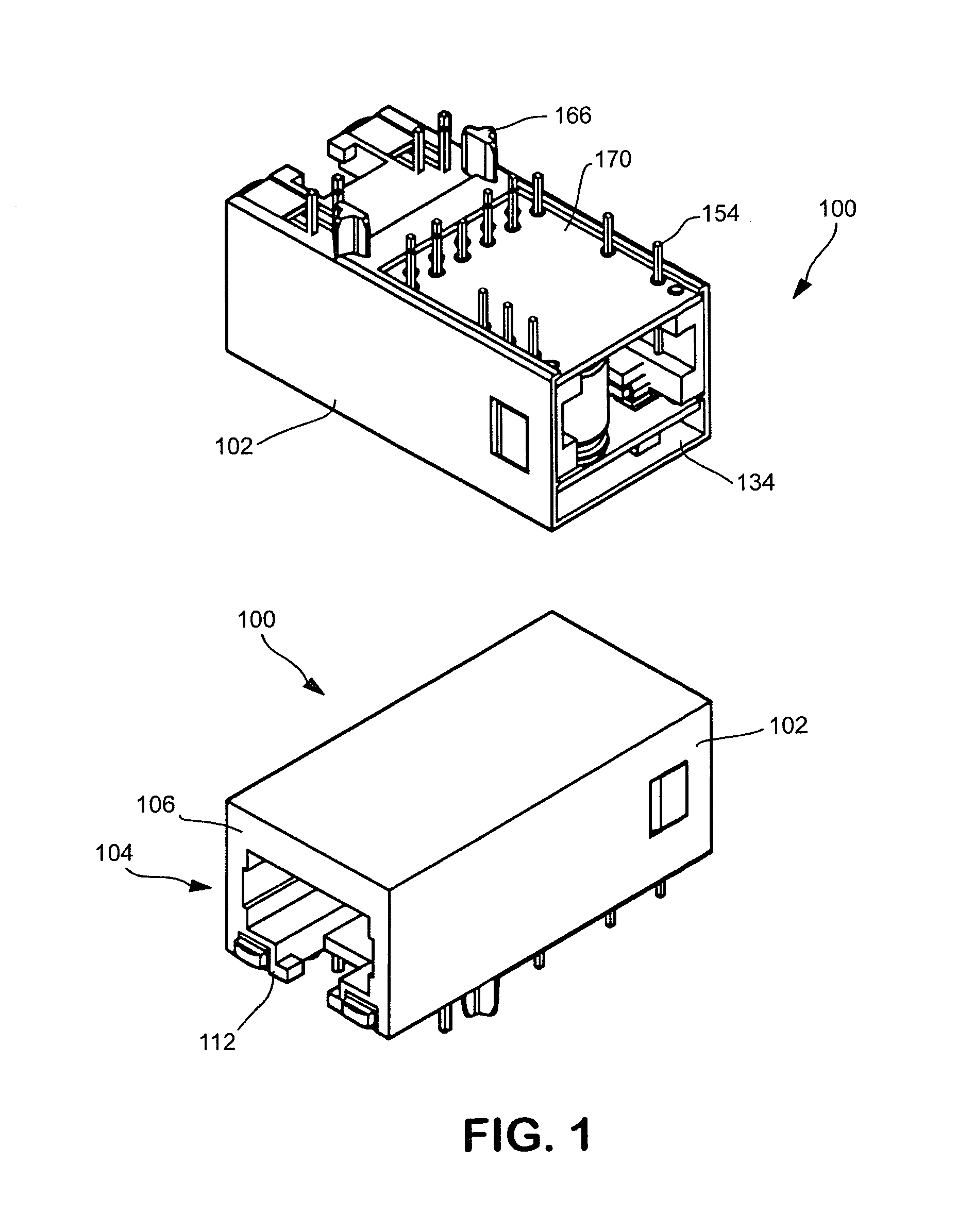
[0070]Single-Port Embodiment Referring now to FIGS. 1-1f, the connector assembly of the present invention is described. It will be appreciated that while described primarily in the context of an RJ-type modular jack (e.g., RJ-45 jack), the invention is in no way limited to such configurations, and may be more broadly applied to other types and form factors of connector.

[0071]As shown in FIG. 1, the exemplary assembly 100 generally comprises a connector housing element 102 having an individual connector 104 formed therein. The front wall 106 of the connector 104 is generally coplanar, such that a modular plug may be inserted into the plug recess 112 formed in the connector 104 without physical interference. Note also that as used herein, the term “front” is relative to the disposition of the connector. For example, in the context of a vertical mounted connector (not shown), the term front wall would more appropriately be described as a “top wall”.

[0072]The plug recess 112 is adapted ...

second embodiment

[0102]The connector assembly 100 with LEDs 190 may further be configured to include noise shielding for the individual LEDs if desired. In one embodiment, the LED shielding is accomplished by forming a thin metallic (e.g., copper, nickel, or copper-zinc alloy, etc.) layer on the interior walls of the LED recesses 194 (or even over the non-conductive portions of LED itself) prior to insertion of each LED. In a second embodiment, a discrete shield element (not shown) which is separable from the connector housing 102 can be used, each shield element being formed so as to accommodate its respective LED and also fit within its respective recess 194. In yet another embodiment, an external noise shield may be fabricated and deformed within the recesses 194 so as to accommodate the LEDs 190 on the outer surface of the shield, thereby providing noise separation between the LEDs and the individual connector conductors 120. A myriad of other approaches for shielding the connectors from the LED...

third embodiment

[0140]FIG. 2c illustrates the invention. In this embodiment, the power control circuitry utilizes two controllers 282, 283 (e.g., PoE integrated circuits, such as the Texas Instruments® TPS2375 devices) connected in parallel. One salient distinguishing feature for this configuration allows the apparatus utilizing this circuitry to handle a higher power output. In the illustrated embodiment, an output power of 30 Watts is achievable (with maximum current input of 350 mA continuous) as opposed to the approximately 15 Watts available under the embodiments shown in FIGS. 2a, 2b. A 4-wire choke 284 between the two bridge rectifier outputs and the controller circuit's inputs may also be utilized, which is especially desirable for EMI suppression. Also, in the exemplary embodiment shown in FIG. 2c, the “power good” outputs 287 are advantageously tied together so that if either output is not available, “power good” status is not asserted. It will be appreciated, however, that other logical ...


PUM


Abstract

An advanced connector assembly enabled to receive and distribute power signals. In one embodiment, the connector comprises a single port modular jack, and incorporates an insert assembly disposed in the rear portion of the connector housing. The insert assembly includes first and second substrates and a cavity adapted to receive one or more electronic or signal conditioning components. Heat removal features are also utilized within the jack to effectively dissipate heat produced by the electronic or signal conditioning components. The insert assembly is also optionally made removable from the jack housing such that an insert assembly of a different electronics or terminal configuration can be substituted therefor. In this fashion, the connector can be configured to a plurality of different standards (e.g., Gigabit Ethernet, 10 / 100, etc.). Methods for manufacturing the aforementioned embodiments are also disclosed.

Description

PRIORITY CLAIM[0001]This application claims priority benefit of co-owned U.S. Provisional Patent Application Ser. No. 60 / 664,873 of the same title filed Mar. 23, 2005, and U.S. Provisional Patent Application Serial No. 60 / 668,411 of the same title filed Apr. 4, 2005, both of which are incorporated herein by reference in their entirety.COPYRIGHT[0002]A portion of the disclosure of this patent document contains material that is subject to copyright protection. The copyright owner has no objection to the facsimile reproduction by anyone of the patent document or the patent disclosure, as it appears in the Patent and Trademark Office patent files or records, but otherwise reserves all copyright rights whatsoever.[0003]1. Field of the Invention[0004]The present invention relates generally to electronic components and particularly to an improved design and method of manufacturing a single- or multi-port connector assembly (e.g., modular jack) that may include internal electronic component...

Claims


Application Information

Patent Timeline
Patent Type & Authority Patents(United States)
IPC IPC(8): H01R13/00H01R13/648
CPCH01R24/64H01R13/6658H01R13/6675H01R2201/04
Inventor GUTIERREZ, AURELIO J.RENTERIA, VICTOR H.MACHADO, RUSSELL L.SCHAFFER, CHRISHINRICHS, HENRY
Owner PULSE ELECTRONICS
Why Eureka
Try Eureka