Active counterforce handle for use in bidirectional deflectable tip instruments

Inactive Publication Date: 2009-04-28
BOSTON SCI SCIMED INC
View PDF13 Cites 34 Cited by
  • Summary
  • Abstract
  • Description
  • Claims
  • Application Information

AI Technical Summary

Benefits of technology

[0010]The present invention is directed to an assembly which provides an active handle for use in a steerable surgical instrument having a shaft deflectable in two directions (bidirectional steering). Typically, the surgical instrument includes a handle component which the user manipulates to cause a distal end of the instrument shaft to deflect in one of two directions. The distal end comprises an end tip portion of the shaft which extends outwardly from the handle. A control mechanism in accordance with the invention is preferably disposed within the handle and extends through the shaft for selectively controlling the direction and degree of deflection at the distal end in one of two directions. For example, one exemplary control mechanism uses control or steering wires to selectively deflect the distal end. The active counterforce mechanism according to the present invention is designed to be used in combination with the control mechanism and provides a force which counters the return to center force generated by the deflection of the shaft at

Problems solved by technology

This results in the user experiencing little if any resistance during

Method used


Image

  • Active counterforce handle for use in bidirectional deflectable tip instruments
  • Active counterforce handle for use in bidirectional deflectable tip instruments
  • Active counterforce handle for use in bidirectional deflectable tip instruments

Examples


first embodiment

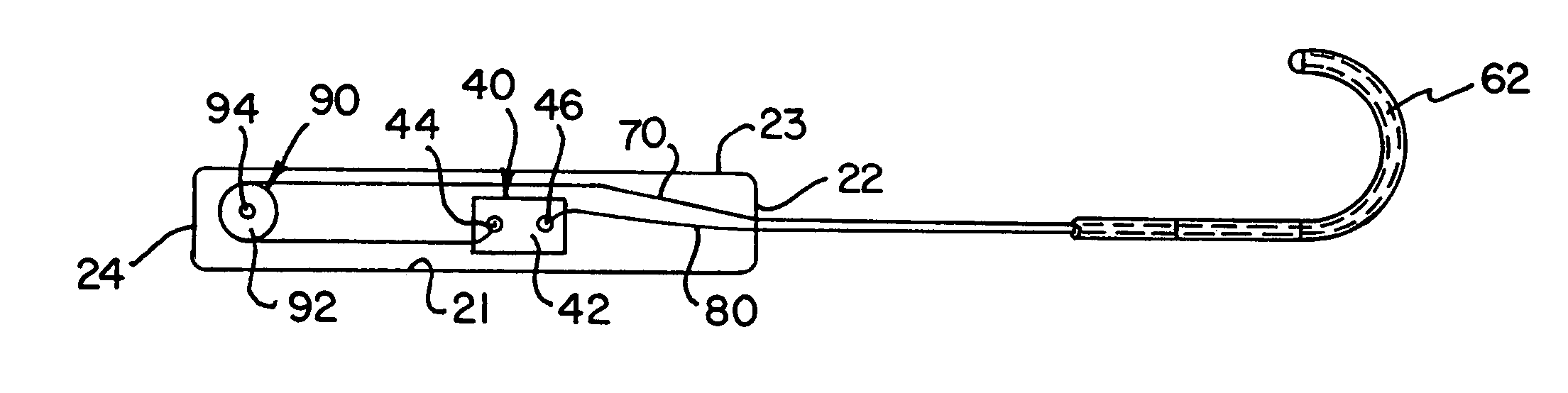
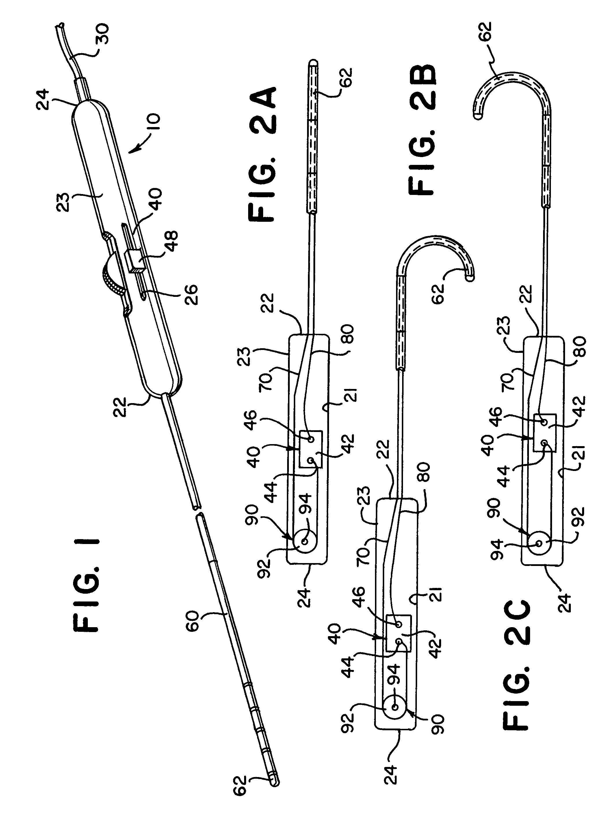
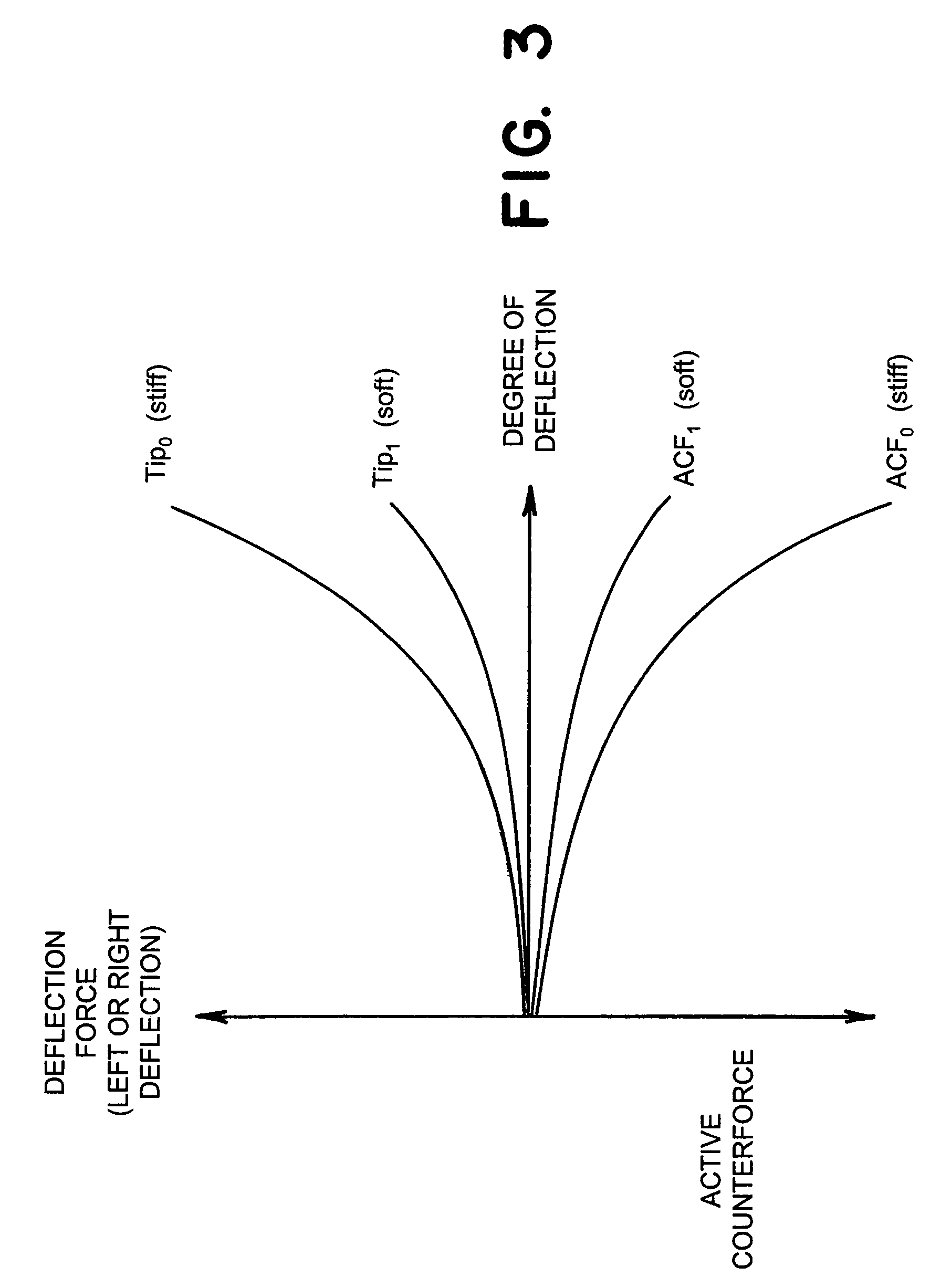
[0033]Now referring to FIGS. 1 and 4A-4C. In accordance with one preferred embodiment of the invention, the active counterforce attributes of the handle 20 are provided by integrating the active counterforce mechanism 50 into the handle 20 in operative combination with the control mechanism 40. FIGS. 4A-4C show the active bidirectional counterforce mechanism 50 according to a Generally, the active bidirectional counterforce mechanism 50 is designed to provide a force to counter the return to center force generated by the catheter shaft 60 as the catheter shaft 60 is deflected in either the first or second directions. This will accordingly assist the user in deflecting the distal end 62 of the catheter shaft 60 over the deflection range of the distal end 62. Optimally, the active counterforce mechanism 50 exactly balances the return to center force from the catheter shaft 60 across its range of motion in the first and second directions resulting in the user experiencing minimal resi...

second embodiment

[0046]Now referring to FIG. 5 in which an active counterforce mechanism is illustrated and generally indicated at 200. The active counterforce mechanism 200 functions generally in the same way as the counterforce mechanism 50 in that it provides a counterforce which balances the return to center force generated by the catheter shaft 60 (FIG. 1). The active counterforce mechanism 200 includes a main traverse bar 210, a first cross bar 220, a second cross bar 230 and a biasing element 240. In FIG. 5, the active counterforce mechanism 200 is shown in a neutral position by solid lines and is shown in proximal and distal positions by phantom lines.

[0047]The main traverse bar 210 has a distal end 212 and an opposing proximal end 214 with the distal end 212 being connected to the slider 42. The proximal end 214 is pivotally connected to the first and second cross bars 220, 230 at a pivot joint 250. More specifically, the first cross bar 220 comprises a lower cross bar and includes a first...

third embodiment

[0053]Now referring to FIG. 6 in which an active counterforce mechanism is generally illustrated and indicated at 300. The active counterforce mechanism 300 is disposed within the compartment 21 of the handle 20 and as in the previously-described embodiments, the mechanism 300 provides a force to counter the catheter force generated by the catheter shaft 60 (FIG. 1) during deflection thereof. The counterforce mechanism 300 includes a traverse bar 310, a biasing element 320, first and second roller bars 330, 340, and first and second rollers 350, 360.

[0054]More specifically, the traverse bar 310 has a distal end 312 connected to the slider 42 and an opposing proximal end 314 connected to the biasing element 320.

[0055]The traverse bar 310 generally extends longitudinally within the compartment 21 of the handle 20. In the illustrated embodiment, the biasing element 320 comprises a torsion spring. The torsion spring 320 has a coiled portion 322 and a pair of linear arms 324, 326 extend...


PUM


Abstract

The present invention is directed to an active handle assembly for use in a bidirectional steerable surgical instrument having a deflectable distal end. Typically, the surgical instrument includes a handle component which the user manipulates to cause a distal end of the instrument to deflect. The distal end comprises an end tip portion of a shaft which extends outwardly from the handle. A control mechanism is disposed within the handle and extends through the shaft for selectively controlling the direction and degree of deflection at the distal end. For example, one exemplary control mechanism uses control or steering wires to deflect the distal end. The active counterforce mechanism according to the present invention is designed to be used in combination with the control mechanism and provides a force which counters the return to center force generated by the deflection of the shaft at the distal end thereof. Optimally, the active counterforce mechanism balances the return to center force across the instrument's deflection range in distal and proximal directions. This results in the user experiencing minimal, if any, resistance during the manual manipulation of the control mechanism.

Description

CROSS REFERENCE TO RELATED APPLICATIONS[0001]This application is a divisional application of copending U.S. patent application Ser. No. 09 / 725,606, filed on Nov. 29, 2000, which is hereby incorporated by reference in its entirety.FIELD OF THE INVENTION[0002]This invention relates to the field of deflectable tip instruments and, more particularly, to an active counterforce handle for use in such instruments to counter a return to center force generated by an instrument shaft upon being deflected.BACKGROUND OF THE INVENTION[0003]Modern surgical procedures often necessitate localized diagnosis, or treatments applied to relatively inaccessible interior areas of the body. In the past, such procedures have typically involved invasive surgery, enabling the physician to visually identify or treat the area of interest by accessing a relatively large opening or incision made in the body. Unfortunately, invasive surgical methods often include undesirable side-effects, from the tissue trauma as...

Claims


Application Information

Patent Timeline
IPC IPC(8): A61M37/00A61M25/01
CPCA61M25/0136A61M25/0147
Inventor DUBOIS, TOMEBERHARDT, MARKMADIA, FRANK
Owner BOSTON SCI SCIMED INC
Why Eureka
Try Eureka