
System and method for creating a networked infrastructure distribution platform of fixed and mobile solar and wind gathering devices

a technology of solar and wind gathering devices and networked infrastructure, which is applied in the direction of wind energy generation, gas pressure propulsion mounting, power supply for propulsion, etc., can solve the problems of limited solar and wind power, no known model of wind power gathering that may be reclaimed, and increased installation does not create a convenient solar infrastructur

Active Publication Date: 2009-04-28
TAMIRAS PER PTE LTD LLC
View PDF68 Cites 18 Cited by
  • Summary
  • Abstract
  • Description
  • Claims
  • Application Information

AI Technical Summary

Benefits of technology

This solution enables widespread, efficient energy generation and distribution, potentially increasing solar's market share to double digits and providing a stable, constant clean energy infrastructure by leveraging roadways for energy capture and distribution, reducing individual investment burdens and environmental impacts.

Problems solved by technology

Isolated uses of solar power are effective, but there incremental installation does not create a convenient solar infrastructure.
As of now, there are no known models for gathering wind power that may be reclaimed from moving vehicles.
Unfortunately, the lack of cohesive solar and wind gathering and distribution resources have limited solar and wind power to a single digit market shares of the overall energy use in the United States.
Wind powered existing conventional uses have certain limitations in distribution and deployment.
Large turbines have faced environmental and Defense Department concerns.
Environmentalists fear that the noise and size of turbines will disrupt both scenic and habitat conditions in addition to threatening the well being of birds that may be caught in the large turbine blades.
Department of Defense concerns have been raised over the large turbines interfering with radar signals and tracking.
Large turbine systems that are placed far away from existing infrastructure also incur a large expense in the transportation or building of infrastructure to carry the power generated by the turbine system.
Finally, the large turbine system represents a large investment for a single turbine that is a volatile investment in that if the wind is not present or wind currents change then the turbine would be viewed as a poor investment because it will not generate enough power.
Also, if the turbine breaks for any reason it is going to produce zero power as it is a large and single entity.
Large turbines also require labor intensive maintenance and monitoring.
The life cycle for large wind turbines is 20 years and decommissioning and waste generated by manufacture, installation and decommissioning is another environmental issue to contend with.
This is a major impediment toward being able to create a large fleet of vehicles gathering energy from small wind and solar gathering mechanisms or devices.
Another impediment is that the power generated from such systems requires a second device or hardware system in order to utilize, receive credit for energy gathered and economically benefit from the power that is derived by the wind and / or solar gathering system.

Method used


Image

  • System and method for creating a networked infrastructure distribution platform of fixed and mobile solar and wind gathering devices
  • System and method for creating a networked infrastructure distribution platform of fixed and mobile solar and wind gathering devices
  • System and method for creating a networked infrastructure distribution platform of fixed and mobile solar and wind gathering devices

Examples


Embodiment Construction

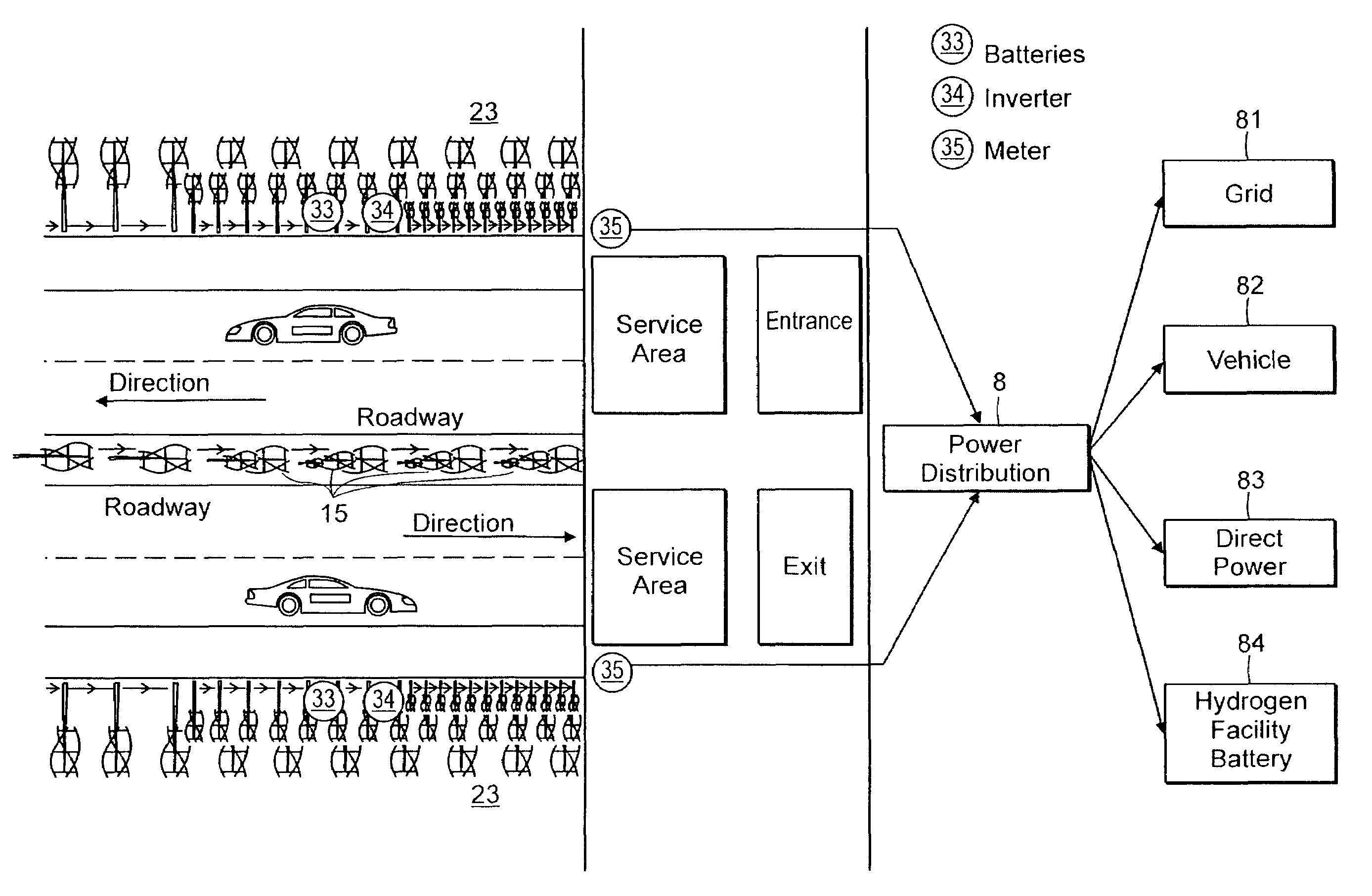
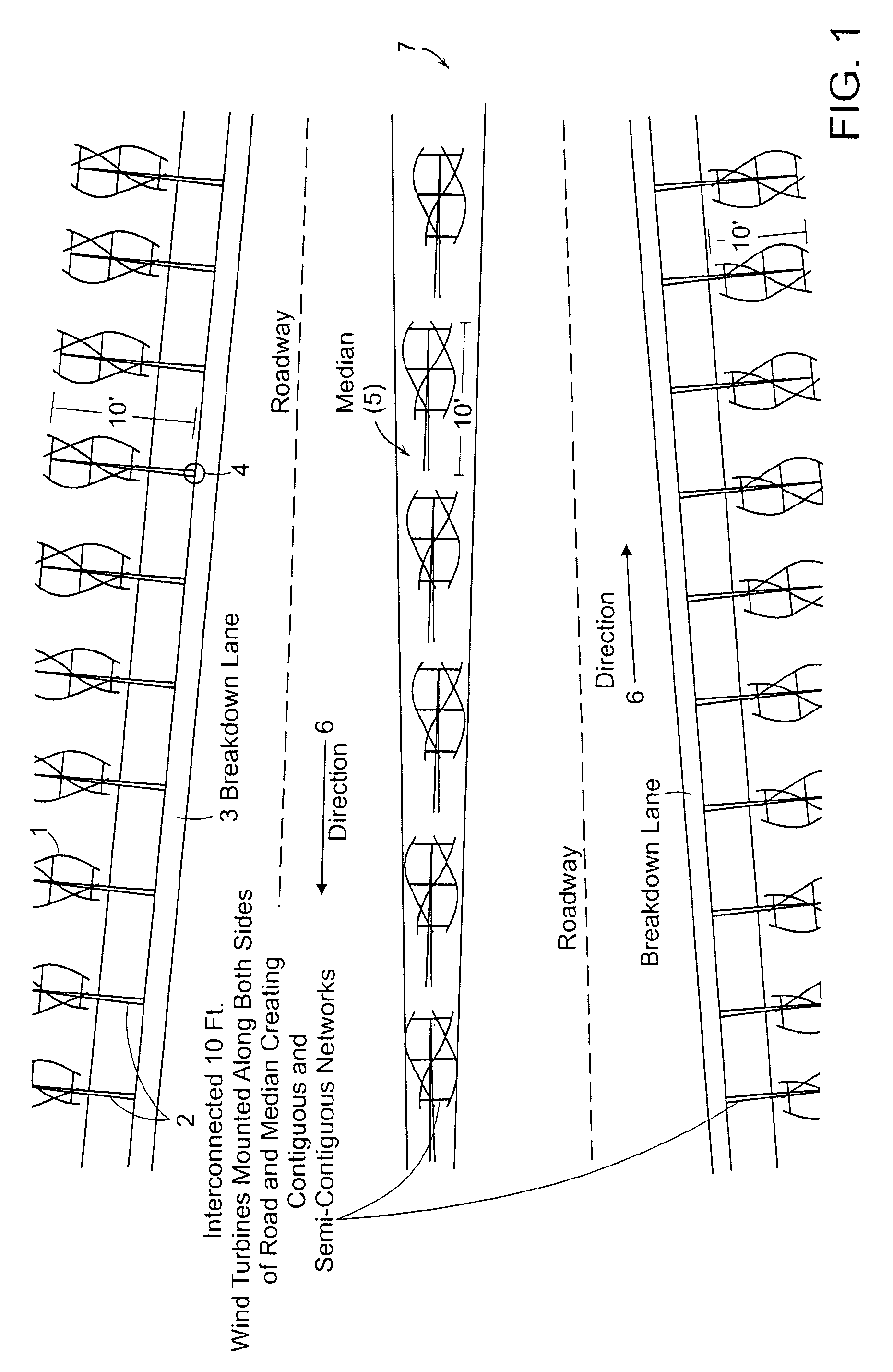
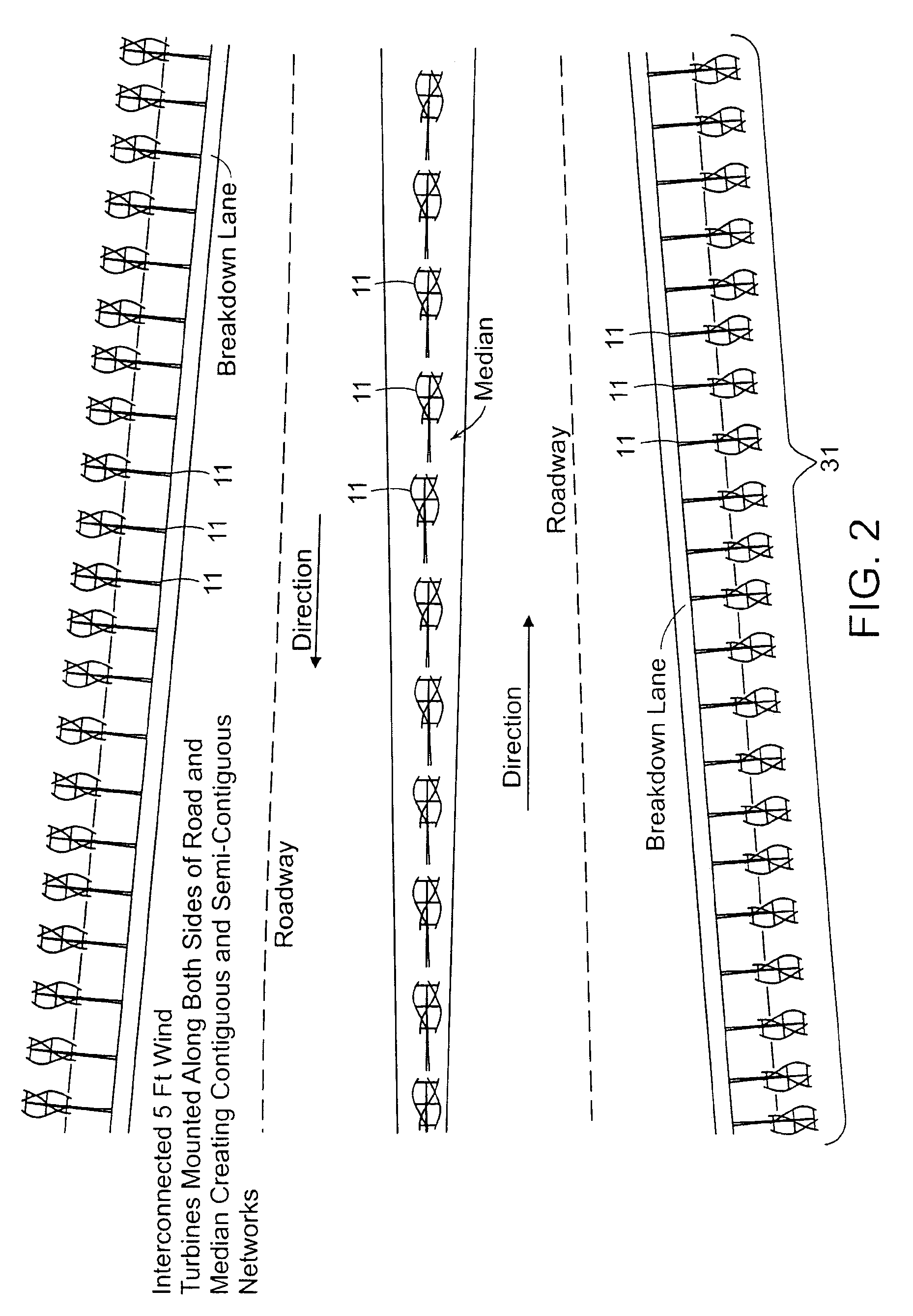
[0048]The present invention provides a roadway system that can provide the basis for a national or global clean or renewable energy infrastructure.

[0049]A “road” (hereinafter also “roadway”) as used herein, is an identifiable route or path between two or more places on which vehicles can drive. A road is typically smoothed, paved, or otherwise prepared to allow easy travel by the vehicles. Also, typically, a road may include one or more lanes, one or more breakdown lanes, one or more medians or center dividers, and one or more guardrails. For example, a road may be highway, turnpike, pike, toll road, state highway, freeway, clearway, expressway, parkway, causeway, throughway, interstate, speedway, autobahn, superhighway, street, railroad, train track, car race tack airplane runway and the like.

[0050]A “vehicle” as used herein, is any device that is used at least partly for ground-based transportation, for example, of goods and / or humans. For example, a vehicle may be an automobile, ...


PUM


Abstract

A roadway system for energy generation and distribution is presented. In accordance with one embodiment of the invention, the roadway system comprises a plurality of ground-based wind energy generating devices, one or more roads, and a roadway system electricity grid. The roadway system may additionally include, for example, a plurality of ground-based solar energy generating devices, one or more vehicle-based solar energy generating devices and one or more vehicle-based wind energy generating devices. The energy generating devices are connected to the roadway system electricity grid and substantially all of the ground-based wind energy generating devices are positioned on part of one of the roads or near to one or more of the roads to thereby allow energy generation from wind created from passing vehicles in addition to energy generation from atmospheric wind.

Description

BACKGROUND OF THE INVENTION[0001]It is well known that solar power is derived by photovoltaic systems, solar panels made from silicon and other materials and thin film solar deployments. Solar power installations where one or more of these solar power gathering unit devices are tied together are referred to as ‘arrays’; are a method of generating clean energy that is used throughout the globe. Solar power generation, as mentioned previously, can come from thin film solar applications, panelized silicon crystal applications and also from passive solar design schemes and many other sources. The cost of solar power gathering systems has gone down in recent years while the efficiency of such systems has continued to improve. It is also well known that wind power turbines can generate power that can be delivered via interconnection to existing grid systems or can be used to power individual homes, businesses and utilities. Most, if not all wind power systems that are used to gather large...

Claims


Application Information

Patent Timeline
Patent Type & Authority Patents(United States)
IPC IPC(8): F03D9/00
CPCB60K16/00B60L8/006F03D9/002F03D9/007F03D9/021F24J3/081B60L8/003B60K2016/003B60K2016/006F05B2220/61F05B2240/212F05B2240/9113F05B2240/941F05B2250/25F05B2250/82Y02B10/30Y02B10/70Y02E10/12Y02E10/725Y02E70/10Y02T10/6269Y02T10/7083Y02T10/90Y02E10/728B60L2200/26F03D9/11F03D9/25F03D9/32F03D9/46F03D9/257F24T10/10H02S10/12Y02E10/10Y02E10/50Y02E10/72Y02E60/36Y02E70/30Y02T10/62Y02T10/7072
Inventor FEIN, GENE S.MERRITT, EDWARD
Owner TAMIRAS PER PTE LTD LLC
Learn More