Bicone pattern shaping device

a pattern shaping and bicone technology, applied in the direction of antennas, antenna feed intermediates, electrical devices, etc., can solve the problems of reducing the availability of external lens elements for all bicone systems, and reducing the mechanical robustness of the antenna assembly. , to achieve the effect of reducing material costs, material handling costs, and manufacturing costs

Active Publication Date: 2009-04-28
EMS TECHNOLOGIES
View PDF7 Cites 248 Cited by
  • Summary
  • Abstract
  • Description
  • Claims
  • Application Information

AI Technical Summary

Benefits of technology

[0007]The present invention comprises a broadband omni-directional bicone antenna. The inventive antenna typically comprises conical voids provided within a single dielectric body. The surfaces of the conical voids can be metallized to provide conductive cone antenna elements. The outside surface of the dielectric body can support radio frequency (RF) lens structures operable for beam forming. The beam forming achieved by the lens can modify the elevation pattern of the radiation from the bicone antenna. The dielectric body may be machined or molded from a single piece of material to provide both the conical voids as well as the beam shaping lenses. Machining from a single piece of material may reduce material costs, material handling costs, and manufacturing costs.
[0008]The outer surface beam shaping lenses can be zoned or continuous and can provide elevation patterns with increased gain, cosecant squared falloff, or various other patterns. The beam forming lens may be formed from any low-loss dielectric. Alternatively, the lens may be formed from a less dense material such as dielectric foam that can support radial conductive beam forming vanes.

Problems solved by technology

These external elements may involve additional handling, manufacturing, cost, and complication.
They may also reduce mechanical robustness of an antenna assembly.
Furthermore, external lens elements may not be available for all bicone systems and may not fulfill specific elevation shaping requirements.

Method used


Image

  • Bicone pattern shaping device
  • Bicone pattern shaping device
  • Bicone pattern shaping device

Examples


Embodiment Construction

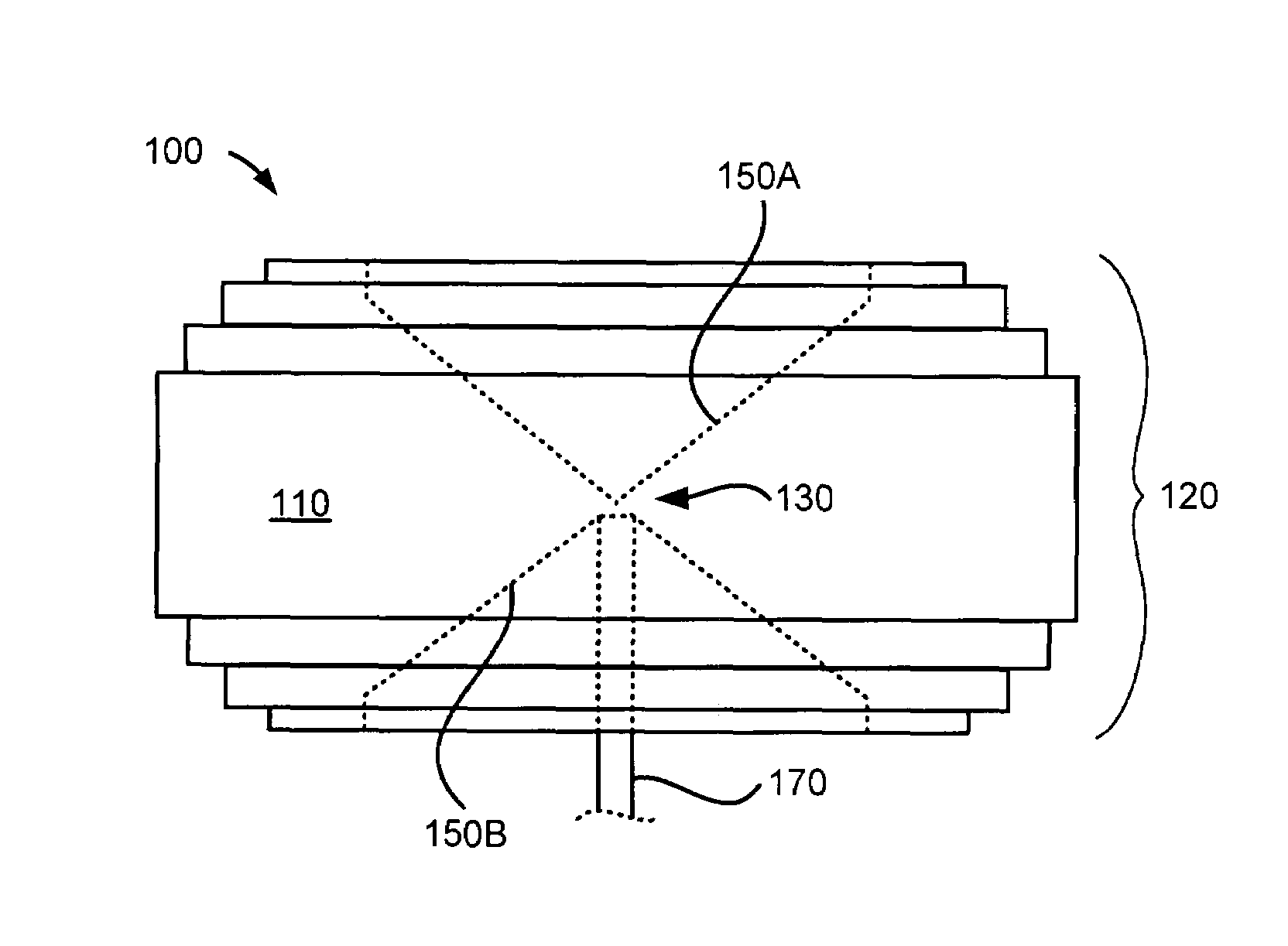
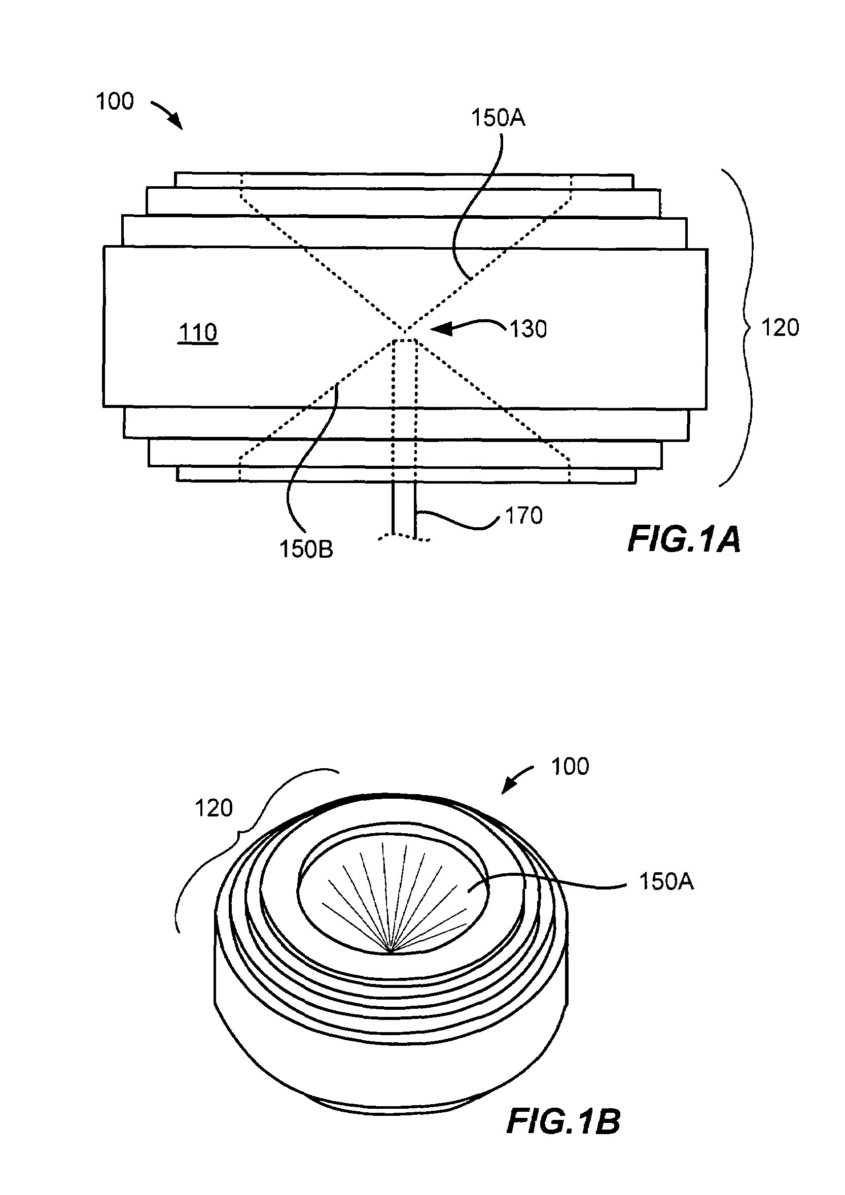
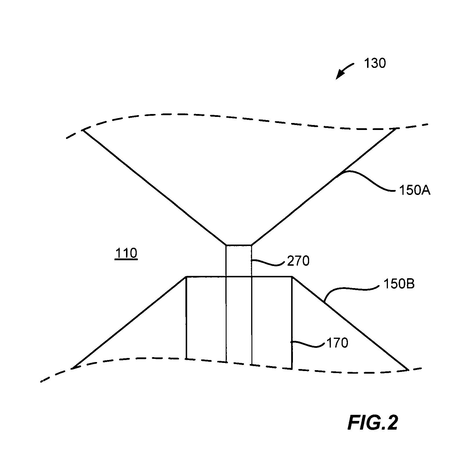
[0017]The present invention supports a broadband omni-directional bicone antenna comprising conical voids provided within a dielectric structure. The surfaces of the conical voids can be metallized to form conductive cone antenna elements. The outside surface of the dielectric structure can be shaped as radio frequency (RF) lens structures operable for beam forming. The beam forming can modify the elevation pattern of the radiation from the bicone antenna. The dielectric structure may be machined or molded from a single piece of material to provide both the conical voids as well as the beam shaping lenses.

[0018]The outer surface beam shaping lenses can be zoned or continuous and can provide elevation patterns with increased gain, cosecant squared falloff, or various other patterns. The beam forming lens may be formed from any low-loss dielectric. Alternatively, the lens may be formed from a less dense material such as dielectric foam that can support radial conductive beam forming v...


PUM


Abstract

A broadband omni-directional bicone antenna. The antenna can comprise conductive surfaces of conical voids provided within a solid dielectric structure. The outside surface of the solid structure can support a radio frequency (RF) lens geometry operable for beam forming. The beam forming can modify the elevation pattern of the electromagnetic radiation from the bicone antenna. The solid dielectric structure may be machined or molded from a single piece of material. The conical voids provided within the solid structure can be metallized to provide conductive bicone radiators. The outer surface beam shaping lenses can be zoned or continuous and can provide elevation patterns with increased gain, cosecant squared falloff, or various other patterns. The beam shaping lens may be formed from any low-loss dielectric. Alternatively, the lens may be formed from a less dense material such as dielectric foam that can support radial conductive beam forming vanes.

Description

RELATED APPLICATION[0001]This patent application claims priority under 35 U.S.C. §119 to U.S. Provisional Patent Application No. 60 / 772,232, entitled “Bicone Pattern Shaping Device,” filed Feb. 10, 2006. The complete disclosure of the above-identified priority application is hereby fully incorporated herein by reference.FIELD OF THE INVENTION[0002]The present invention relates to an omni-directional bicone antenna and more specifically to an antenna having two cone-shaped antenna elements and a beam shaping lens formed within a single blank of dielectric material.BACKGROUND[0003]A bicone is generally an antenna having two conical conductors, where the conical elements share a common axis, and a common vertex. The conical conductors extend in opposite directions. That is, the two flat portions of the cones face outward from one another. The flat portion of the cone can also be thought of as the base of the cone or the opening of the cone. The flat portion, or opening, of a cone is at...

Claims


Application Information

Patent Timeline
Patent Type & Authority Patents(United States)
IPC IPC(8): H01Q13/00H01Q15/02
CPCH01Q9/28H01Q19/062
Inventor BLACK, DONALD N.NEWBURY, TERENCE D.JONES, ALANPARR, R. DEANBUNCE, BAYNE
Owner EMS TECHNOLOGIES
Why Eureka
Try Eureka