Fireguard circuit

a safety device and circuit technology, applied in emergency protective arrangements, emergency protective arrangements for limiting excess voltage/current, electrical equipment, etc., can solve problems such as ground fault and ground neutral conditions in conducting lines, and create a number of potentially dangerous conditions

Inactive Publication Date: 2009-04-28
TOWER MFG
View PDF37 Cites 18 Cited by
  • Summary
  • Abstract
  • Description
  • Claims
  • Application Information

AI Technical Summary

Benefits of technology

[0014]It is yet another object of the present invention to provide a safety circuit as described above which may be mass produced, has a minimal number of parts, and can be easily assembled.
[0015]Accordingly, in one embodiment of the present invention, there is provided a fireguard circuit for use with a power cable, said power cable connecting a power source with a load, said power cable comprising a power line, a neutral line and a metal sheath which surrounds the power line and the neutral line, said fireguard circuit comprising a circuit breaker comprising a first switch located in one of said lines between the power source and the load, said switch having a first position in which the power source in its associated line is connected to the load and a second position in which the power source in its associated line is not connected to the load, a circuit opening device for setting said switch in either its first position or its second position, said circuit opening device being operable in either a first state or a second state, said circuit opening device setting said switch in its first position when in its first state and said circuit opening device setting said switch in its second position when in its second state, a first silicon controlled rectifier (SCR) for detecting the presence of an arcing condition between one of said lines and the metal sheath, said first SCR setting said circuit opening device at its second state upon detecting the presence of an arcing condition between one of said lines and the metal sheath, said first SCR comprising an anode, a cathode and a gate, and a nuisance tripping resistor connected to said first SCR to reduce the likelihood of nuisance tripping in said first SCR.
[0017]In another embodiment of the present invention, there is provided a fireguard circuit for use with a power cable, said power cable connecting a power source with a load, said power cable comprising a power line, a neutral line and a metal sheath which surrounds the power line and the neutral line, said fireguard circuit comprising a circuit breaker comprising a first switch located in one of said lines between the power source and the load, said switch having a first position in which the power source in its associated line is connected to the load and a second position in which the power source in its associated line is not connected to the load, a circuit opening device for setting said switch in either its first position or its second position, said circuit opening device being operable in either a first state or a second state, said circuit opening device setting said switch in its first position when in its first state and said circuit opening device setting said switch in its second position when in its second state, a first silicon controlled rectifier (SCR) for detecting the presence of an arcing condition between one of said lines and the metal sheath, said first SCR setting said circuit opening device at its second state upon detecting the presence of an arcing condition between one of said lines and the metal sheath, said first SCR comprising an anode, a cathode and a gate, a second silicon controlled rectifier (SCR) for detecting the presence of an arcing condition between the other of said lines and the metal sheath, said second SCR setting said circuit opening device at its second state upon detecting the presence of an arcing condition between the other of said lines and the metal sheath, said second SCR comprising an anode, a cathode and a gate, and a zener diode connected to said second SCR to reduce the peak voltage at which the metal sheath biases.
[0018]In another embodiment of the present invention, there is provided a fireguard circuit for use with a power cable, said power cable connecting a power source with a load, said power cable comprising a power line, a neutral line and a metal sheath which surrounds the power line and the neutral line, said fireguard circuit comprising a circuit breaker comprising a first switch located in one of said lines between the power source and the load, said switch having a first position in which the power source in its associated line is connected to the load and a second position in which the power source in its associated line is not connected to the load, a circuit opening device for setting said switch in either its first position or its second position, said circuit opening device being operable in either a first state or a second state, said circuit opening device setting said switch in its first position when in its first state and said circuit opening device setting said switch in its second position when in its second state, a first silicon controlled rectifier (SCR) for detecting the presence of an arcing condition between one of said lines and the metal sheath, said first SCR setting said circuit opening device at its second state upon detecting the presence of an arcing condition between one of said lines and the metal sheath, said first SCR comprising an anode, a cathode and a gate, a second silicon controlled rectifier (SCR) for detecting the presence of an arcing condition between the other of said lines and the metal sheath, said second SCR setting said circuit opening device at its second state upon detecting the presence of an arcing condition between the other of said lines and the metal sheath, said second SCR comprising an anode, a cathode and a gate, and a transistor circuit connected to said second SCR to reduce the peak voltage at which the metal sheath biases.
[0020]In another embodiment of the present invention, there is provided a fireguard circuit for use with a power cable, said power cable connecting a power source with a load, said power cable comprising a power line, a neutral line and a metal sheath which surrounds the power line and the neutral line, said fireguard circuit comprising a circuit breaker comprising a first switch located in one of said lines between the power source and the load, said switch having a first position in which the power source in its associated line is connected to the load and a second position in which the power source in its associated line is not connected to the load, a circuit opening device for setting said switch in either its first position or its second position, said circuit opening device being operable in either a first state or a second state, said circuit opening device setting said switch in its first position when in its first state and said circuit opening device setting said switch in its second position when in its second state, a first silicon controlled rectifier (SCR) for detecting the presence of an arcing condition between one of said lines and the metal sheath, said first SCR setting said circuit opening device at its second state upon detecting the presence of an arcing condition between one of said lines and the metal sheath, said first SCR comprising an anode, a cathode and a gate, and a zener diode connected to the metal sheath to reduce voltage bias in the metal sheath.

Problems solved by technology

The connection of an electrical appliance to a power supply through a pair of conducting lines can create a number of potentially dangerous conditions.
In particular, there exists the risk of ground fault and grounded neutral conditions in the conducting lines.
A ground fault condition occurs when there is an imbalance between the currents flowing in the power and neutral lines.
The second voltage is sufficient to maintain the solenoid in its energized state after being initially energized by the first voltage but is insufficient to switch the solenoid from its de-energized state to its energized state.
While GFCI circuits of the type described above are well known and widely used in commerce to protect against ground fault and grounded neutral conditions, it should be noted that a power cable is susceptible to other types of hazardous conditions which are not protected against by a conventional GFCI circuit.
It should be noted that the presence of this type of arcing condition between either the power line and the metal sheath or the neutral line and the metal sheath can result in a fire or other dangerous condition, which is highly undesirable.
Although well known in commerce, the GFCI disclosed in Legatti suffers from a notable drawback.
As can be appreciated, the implementation of a differential transformer significantly increases the overall size and cost of the product, which is highly undesirable.

Method used


Image

  • Fireguard circuit
  • Fireguard circuit
  • Fireguard circuit

Examples


first embodiment

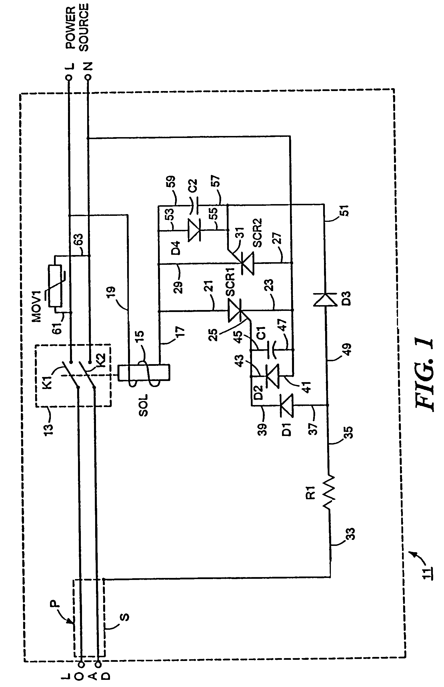
[0045]Referring now to FIG. 1, there is shown a fireguard circuit constructed according to the teachings of the present invention, the fireguard circuit being represented generally by reference numeral 11. Fireguard circuit 11 is designed principally for use as a safety device for a power cable P which connects a power source (i.e., a line) to a load, said power cable P including a power line L and a neutral line N. Each of the power and neutral lines L and N is wrapped with a metal sheath or other similar type of shielded wrapping. The metal sheaths of the power and neutral lines L and N are, in turn, twisted together so as to effectively form a single metal sheath S which surrounds power line L and neutral line N.

[0046]As will be discussed in detail below, fireguard circuit 11 interrupts the flow of current through power line L and neutral line N extending between the power source and the load when an arcing condition occurs either between power line L and metal sheath S or betwee...

second embodiment

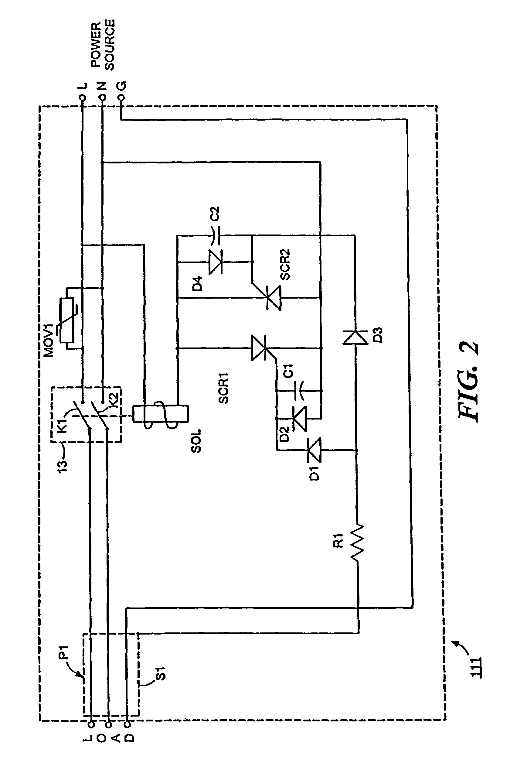
[0066]It should also be noted that, although fireguard circuit 11 is shown for use as a safety device for a power cable which comprises two conducting lines, it is to be understood that fireguard circuit 11 could also be used as a safety device for a power cable which comprises three conducting lines without departing from the spirit of the present invention. Specifically, referring now FIG. 2, there is shown a fireguard circuit constructed according to the teachings of the present invention, the fireguard circuit being represented generally by reference numeral 111.

[0067]Fireguard circuit 111 (which is also referred to herein as safety circuit 111) is identical in all respects with fireguard circuit 11 except for the fact that fireguard circuit 111 is designed principally for use as a safety device for a power cable P1 which includes three conducting lines whereas fireguard circuit 11 is designed principally for use as a safety device for a power cable P which includes two conducti...

third embodiment

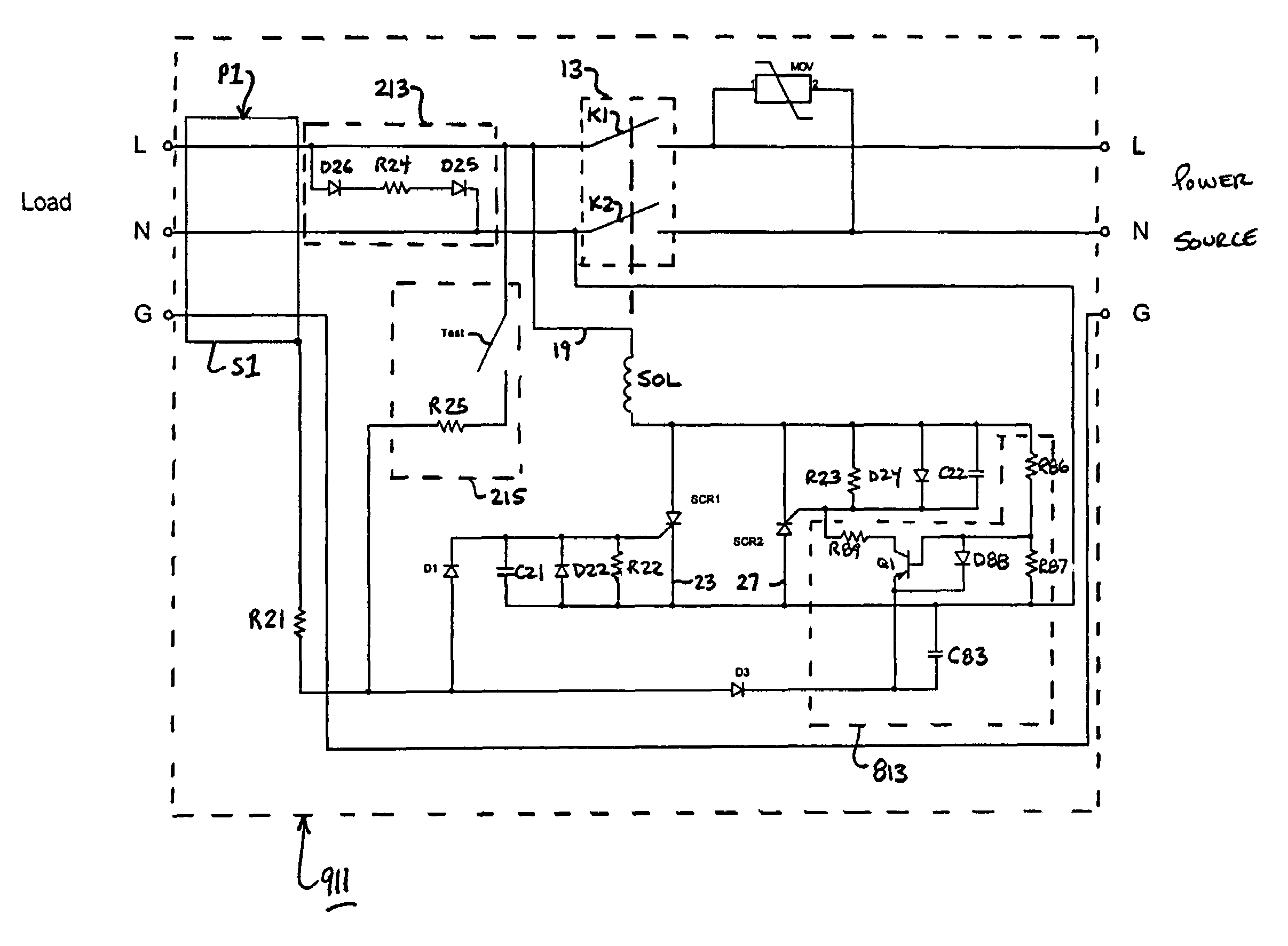
[0068]Referring now FIG. 3, there is shown a fireguard circuit constructed according to the teachings of the present invention, the fireguard circuit being represented generally by reference numeral 211.

[0069]Fireguard circuit 211 (which may also be referred to herein as safety circuit 211) is identical in all respects with fireguard circuit 111 with four primary distinctions, as will be enumerated below.

[0070]First, the preferred value and / or model type of selected components in fireguard circuit 111 are modified slightly in fireguard circuit 211. Specifically, voltage dropping resistor R1 in fireguard circuit 111 is replaced with a voltage dropping resistor R21 in fireguard circuit 211, voltage dropping resistor R21 preferably having a value of approximately 15 Kohms. In addition, protection diodes D2 and D4 in fireguard circuit 111 are replaced with protection diodes D22 and D24, respectively, in fireguard circuit 211, each of protection diodes D22 and D24 preferably having a mod...


PUM


Abstract

A fireguard circuit for a power cable, which comprises a power line, a neutral line and a metal sheath surrounding the power line and the neutral line, includes a switch located in one of the lines. A solenoid sets the switch in either an open position or a closed position. A first silicon controlled rectifier (SCR) causes the solenoid to open the switch upon detecting the presence of an arcing condition between the power line and the metal sheath. A second silicon controlled rectifier (SCR) causes the solenoid to open the switch upon detecting the presence of an arcing condition between the neutral line and the metal sheath. The second SCR is connected in parallel with the first SCR, the anode of the first SCR being connected to the cathode of the second SCR and the cathode of the first SCR being connected to the anode of the second SCR.

Description

CROSS-REFERENCE TO RELATED APPLICATIONS[0001]The present application is a continuation-in-part of application Ser. No. 10 / 102,539 filed Mar. 27, 2002, now U.S. Pat. No. 6,738,241 which issued in the name of Victor V. Aromin on May 18, 2004, and U.S. patent application Ser. No. 10 / 783,966 which was filed on Feb. 20, 2004 now abandoned in the name of Victor V. Aromin, and U.S. patent application Ser. No. 10 / 846,358 which was filed on May 13, 2004 now abandoned in the name of Victor V. Aromin, the disclosures of all being incorporated herein by reference.BACKGROUND OF THE INVENTION[0002]The present invention relates generally to electrical safety devices and more particularly to electrical safety devices for a power cable.[0003]Conventional electrical appliances typically receive alternating current (AC) power from a power source, such as an electrical outlet, through a power cable. The power cable enables the electrical appliance, or load, to receive from the power source the current ...

Claims


Application Information

Patent Timeline
Patent Type & Authority Patents(United States)
IPC IPC(8): H02H3/00H02H9/08H02H1/00H02H7/22
CPCH02H1/0015H02H7/222H02H7/228
Inventor AROMIN, VICTOR V.
Owner TOWER MFG
Why Eureka
Try Eureka