
Three-dimensional CAD system and part cost calculation system

a three-dimensional cad system and calculation system technology, applied in the direction of process and machine control, instruments, computer control, etc., can solve the problems of die cost, die weight, production cost of parts formed by dies, etc., and achieve the effect of accurately calculating the cost of a given par

Inactive Publication Date: 2009-04-28
HONDA MOTOR CO LTD
View PDF8 Cites 38 Cited by
  • Summary
  • Abstract
  • Description
  • Claims
  • Application Information

AI Technical Summary

Benefits of technology

[0014]The parts cost calculation system according to the second aspect of the present invention may accurately calculate the cost of a given part based on the cost factors of the die involved with such as a projected area of the part on a plane perpendicular to the drafting direction of the die as well as a total length of the part in that drafting direction.

Problems solved by technology

The production costs of parts formed by dies are dependent not only on the size, weight, material and shapes of the parts but also on the cost of the dies to a considerable extent.
The bulkier and heavier the dies, the higher their costs.
Because conventional systems typically received two-dimensional data from an outside source as mentioned above, if the drafting direction is established anywhere other than with respect to the front, on the side or on top of the die, such a system has a difficulty in calculating the projected area of the part or the depth of the die involved.

Method used


Image

  • Three-dimensional CAD system and part cost calculation system
  • Three-dimensional CAD system and part cost calculation system
  • Three-dimensional CAD system and part cost calculation system

Examples


Embodiment Construction

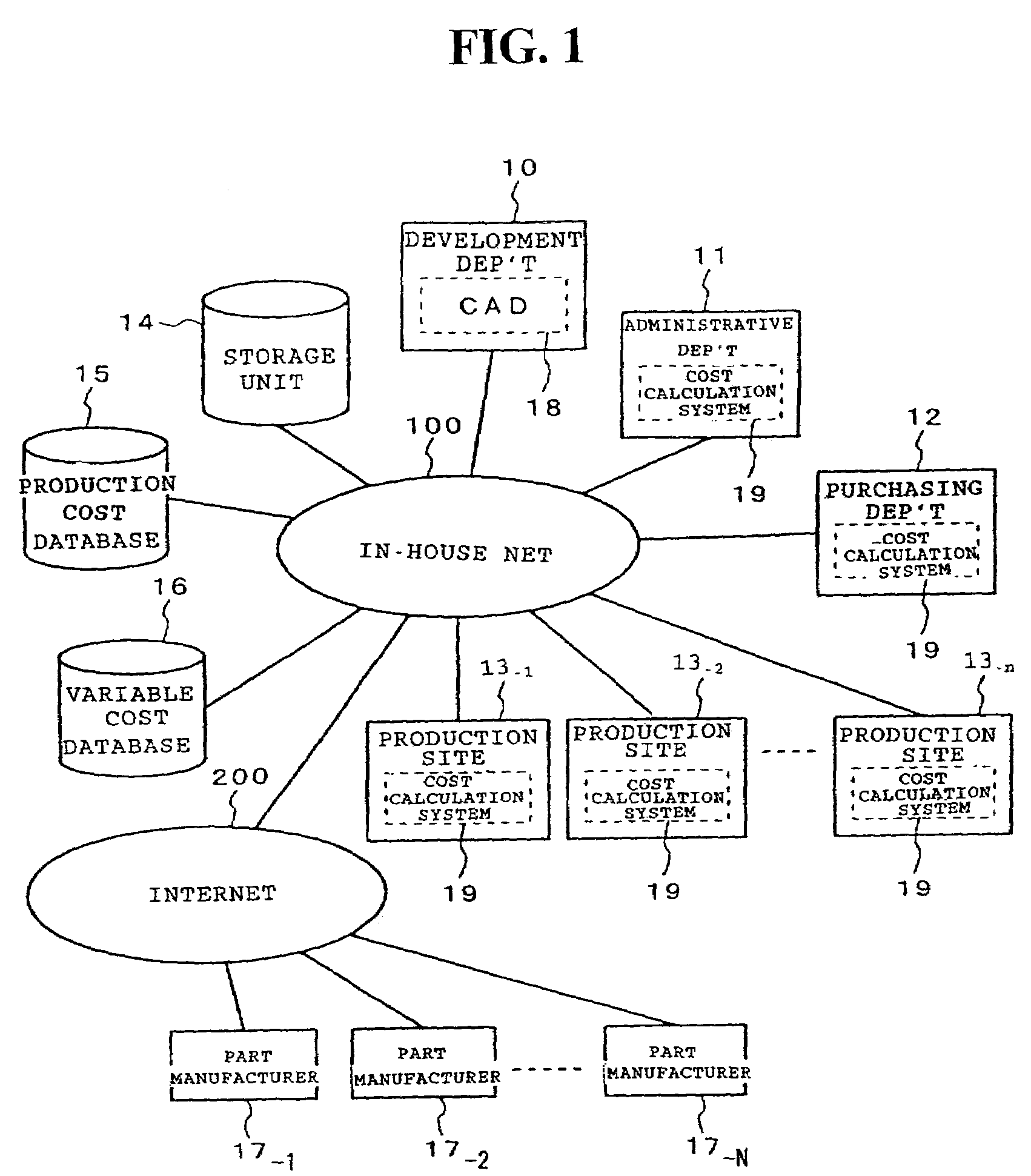
[0024]Preferred embodiments of the present invention will now be described by referring to the accompanying drawings. FIG. 1 is a network diagram showing a three-dimensional CAD system and a parts cost calculation system according to the present invention.

[0025]In the setup of FIG. 1, a Development Department 10 includes a three-dimensional CAD system 18. An Administrative Department 11, a Purchasing Department 12 and production sites 13-1, 13-2, . . . , 13-n (generically called the In-house Production Department 13 as a group hereunder) are each equipped with an information processing terminal such as a personal computer acting as a cost calculation system 19. These information processing terminals are connected to a network such as a LAN, an intranet or an extranet (called the in-house net hereunder) 100.

[0026]The in-house net 100 is also connected with storage units 14, 15 and 16 for accommodating data. The storage unit 14 stores shape data and other relevant data about parts to ...


PUM

PropertyMeasurementUnit
Areaaaaaaaaaaa
Depthaaaaaaaaaa

Abstract

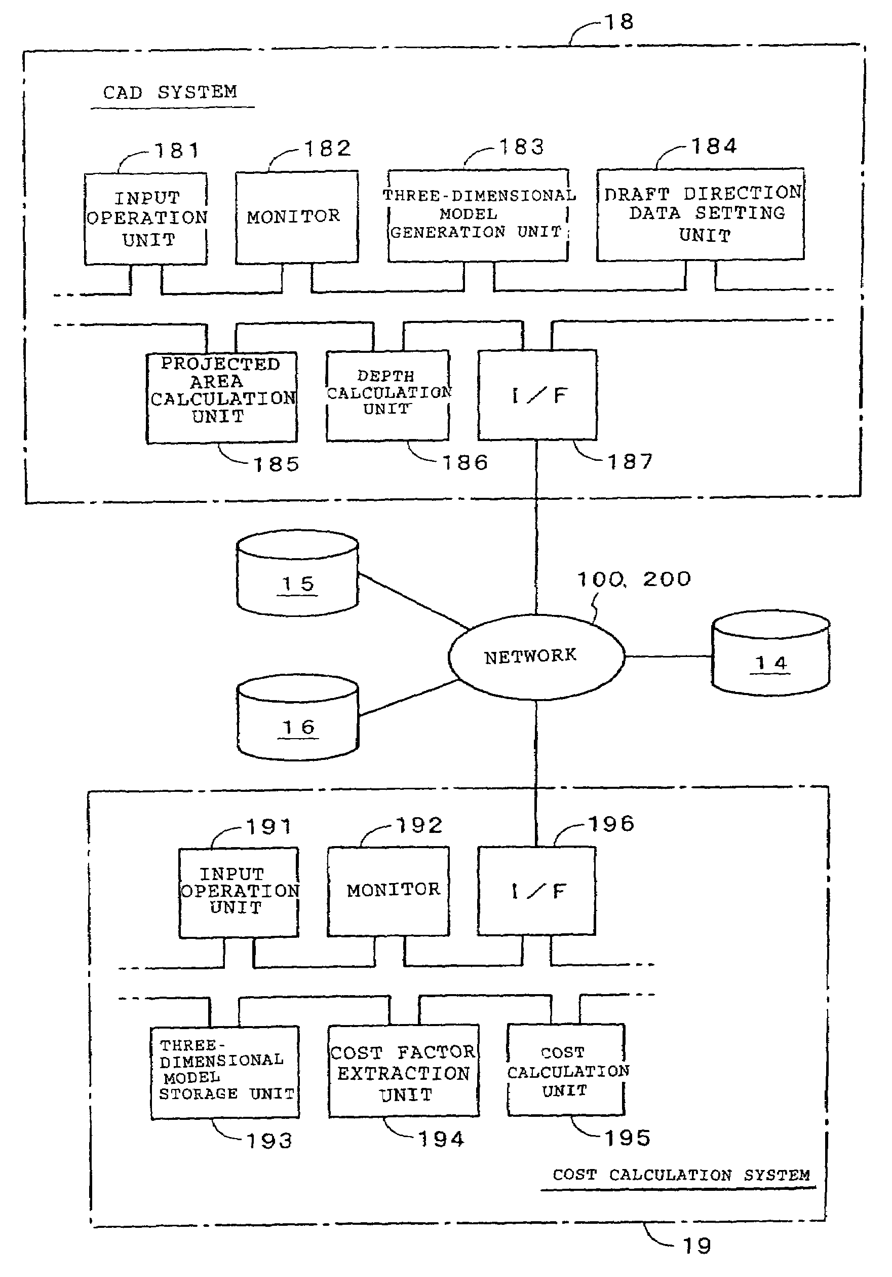
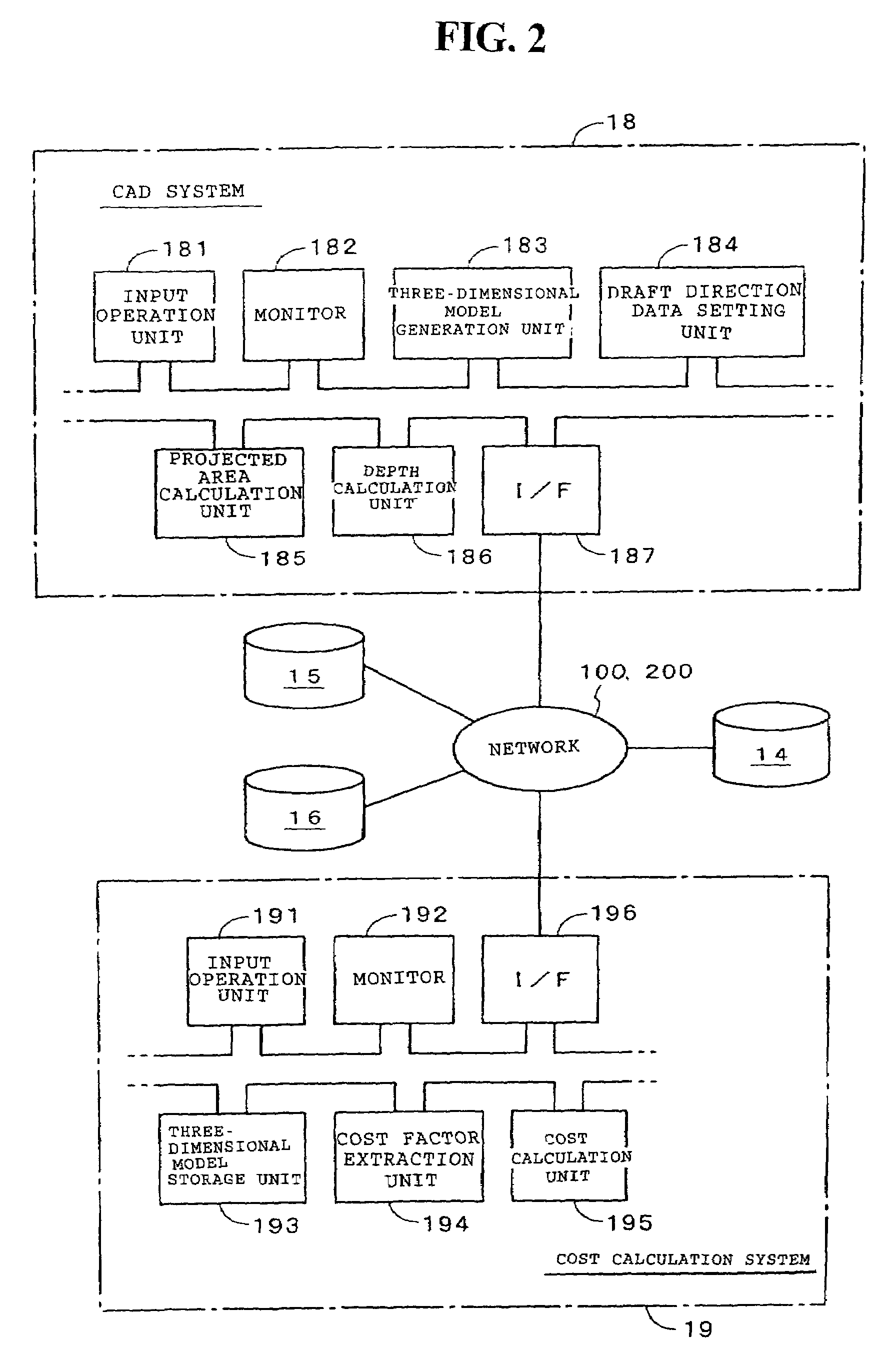
An object of the present invention is to provide a three-dimensional CAD-system for adding data about a drafting direction of a die to three-dimensional data about the part to be formed by that die, and a cost calculation system for calculating the cost of the part based on that drafting direction data. A three-dimensional model generation unit of a CAD system generates: a three-dimensional shaped model of a given part based on information coming from an input operation unit. A drafting direction data setting unit establishes drafting direction data when the input operation unit is operated to designate the drafting direction of the die for press molding, injection molding or the like of the part in question. A projected area calculation unit calculates a projected area S of the part on a plane perpendicular to the drafting direction of the applicable die on the basis of the three-dimensional model of that part and the drafting direction data involved. A depth calculation unit calculates a depth D of the part in the relevant drafting direction.

Description

CROSS-REFERENCE TO RELATED APPLICATIONS[0001]The present application claims priority under 35 USC 119 to Japanese Patent Application No. 2001-154507 filed on May 23, 2001 the entire contents thereof is hereby incorporated by reference.BACKGROUND OF THE INVENTION[0002]1. Field of the Invention[0003]The present invention relates to a three-dimensional CAD system and a parts cost calculation system for calculating production costs of parts to be formed by dies based on three-dimensional data about the parts in question. More particularly, the invention relates to a three-dimensional CAD system and a parts cost calculation system for calculating costs of parts in consideration of their drafting directions.[0004]2. Description of Background Art[0005]In recent years there has been a widespread use of systems for calculating costs of parts using computers. For example, Japanese Patent Laid-open No. Hei 9-160945 discloses a system that receives two-dimensional data about parts from a CAD sy...

Claims


Application Information

Patent Timeline
IPC IPC(8): G06F19/00G06F3/00G06G7/00G06F17/50
CPCG06F17/50G06Q30/0283G06F30/00
Inventor KAWANO, AKIOIWAI, KAZUHIROSHIMIZU, MASAKATSUYAMAMOTO, EIJI
Owner HONDA MOTOR CO LTD
Learn More