Electrically controlled suspension system

a suspension system and electric control technology, applied in the direction of underwater vessels, non-deflectable wheel steering, navigation instruments, etc., can solve the problems of deteriorating ride comfort and deteriorating ride comfort, and achieve the effect of ensuring ride comfort and controlling stability

Active Publication Date: 2009-04-28
HL MANDO CORP
View PDF11 Cites 21 Cited by
  • Summary
  • Abstract
  • Description
  • Claims
  • Application Information

AI Technical Summary

Benefits of technology

[0010]The present invention is conceived to solve the aforementioned problems in the prior art. Accordingly, an object of the present invention is to provide an electronically controlled suspension system, wherein a control command value for use in controlling a damping force of a damper is calculated by employing a nonlinear control gain according to a signal outputted from a vertical acceleration sensor, thereby securing ride comfort and control stability.

Problems solved by technology

Thus, there is a problem in that ride comfort is deteriorated.

Method used


Image

  • Electrically controlled suspension system
  • Electrically controlled suspension system

Examples


Embodiment Construction

[0016]Hereinafter, a preferred embodiment of the present invention will be described in detail with reference to the accompanying drawings.

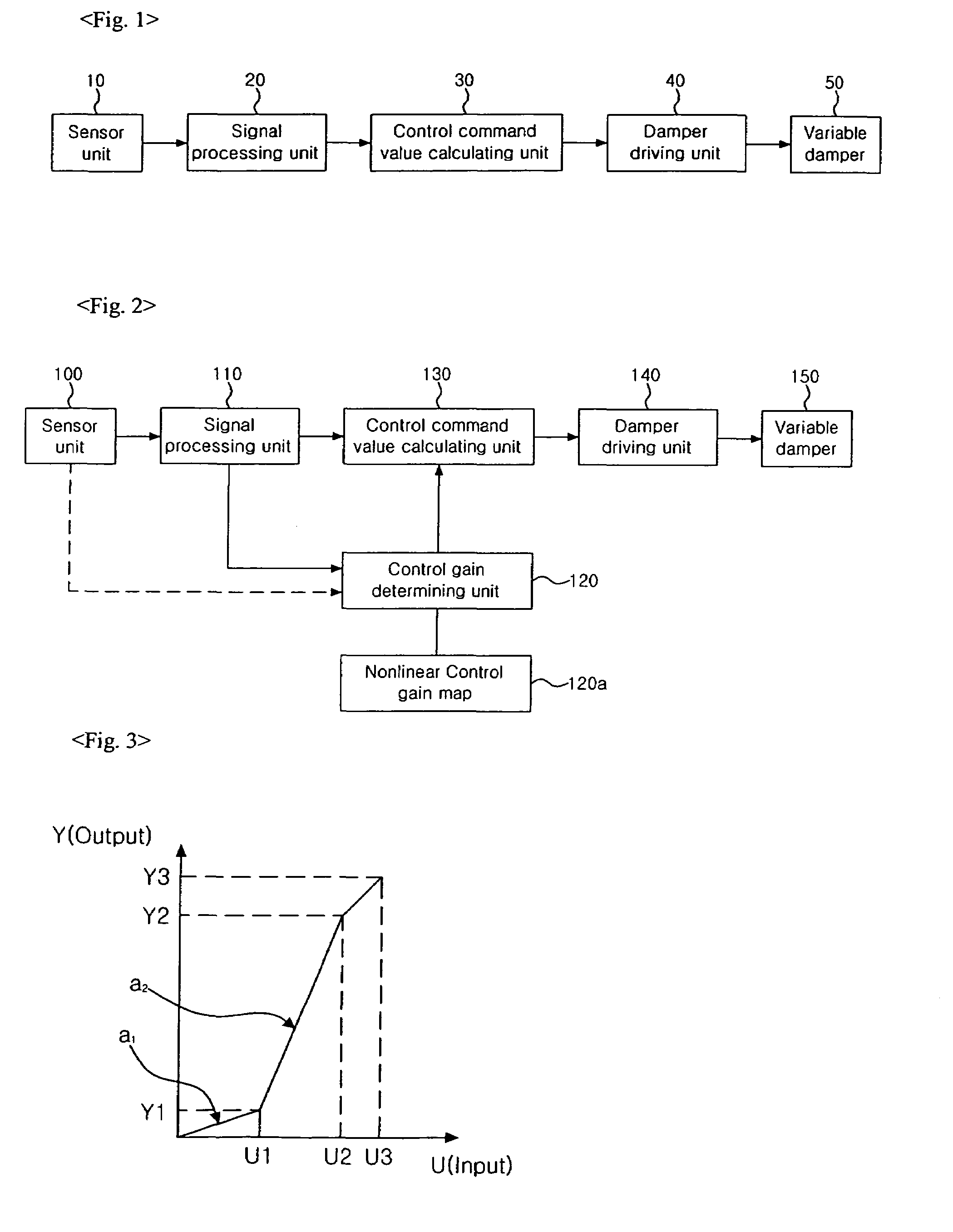
[0017]FIG. 2 is a block diagram illustrating an electronically controlled suspension system according to the present invention, and FIG. 3 is a view illustrating a nonlinear control gain map for use in calculating a control gain in the present invention.

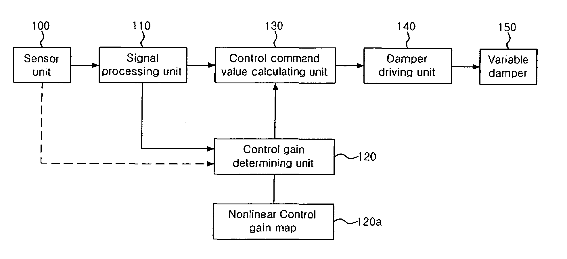
[0018]Referring to FIG. 2, the electronically controlled suspension system according to the present invention comprises a sensor unit 100, a signal processing unit 110, a control gain determining unit 120, a control command value calculating unit 130, damper driving units 140, and variable dampers 150.

[0019]The sensor unit 100 detects vertical acceleration components of a vehicle using vertical acceleration sensors mounted at portions of a vehicle body on the sides of front and rear, right and left road wheels and provides them to the signal processing unit 110. The signal processing unit 110 calc...


PUM


Abstract

An electronically controlled suspension system according to the present invention comprises a sensor unit for extracting and providing a vertical acceleration component of a vehicle body of a vehicle; a signal processing unit for calculating a vertical velocity of the vehicle body using the vertical acceleration component provided by the sensor unit; a control gain determining unit having a control gain set according to the amplitude of the vertical acceleration component, and detecting the amplitude of the vertical acceleration component provided by the sensor unit and extracting a control gain corresponding to the detected amplitude; a control command value calculating unit for calculating a control command value using the control gain provided by the control gain determining unit and the vertical velocity of the vehicle body provided by the signal processing unit; and a damper driving unit for driving the variable damper based in the control command value.According to the present invention described above, a control command value for use in controlling a damping force of a damper is calculated using a nonlinear control gain according to a signal outputted from a speed or vertical acceleration sensor, thereby securing ride comfort and control stability.

Description

BACKGROUND OF THE INVENTION[0001]1. Field of the Invention[0002]The present invention relates to an electronically controlled suspension system, and more particularly, to an electronically controlled suspension system capable of securing ride comfort and control stability.[0003]2. Description of the Related Art[0004]Generally, a suspension system is a shock-absorbing apparatus comprising a shock absorber or spring installed between an axle and a frame of a vehicle, and serves to make the vertical movement of the vehicle smooth and to absorb a shock or vibration transmitted from a road surface so that the shock or vibration cannot be transmitted to a vehicle body of the vehicle.[0005]Hereinafter, a conventional electronically controlled suspension system will be described with reference to the accompanying drawings. FIG. 1 is a block diagram illustrating a conventional electronically controlled suspension system.[0006]As illustrated in FIG. 1, the electronically controlled suspension...

Claims


Application Information

Patent Timeline
Patent Type & Authority Patents(United States)
IPC IPC(8): G06F1/00A01B69/00
CPCB60G17/015B60G17/0152B60G17/08B60G2400/102B60G2400/202B60G2400/82B60G2500/10B60G2800/702
Inventor KIM, WAN ILLEE, JEONG WOO
Owner HL MANDO CORP
Why Eureka
Try Eureka