Motor controller that uses an acceleration/deceleration time constant of the motor

a technology of motor controller and acceleration/deceleration time constant, which is applied in the direction of program control, total factory control, instruments, etc., can solve the problems of vibration, inability to change the command trajectory, and the position control of the motor may become unstable, so as to improve the efficiency of machining and ensure the stability of control

Active Publication Date: 2021-03-16
FANUC LTD
View PDF40 Cites 0 Cited by
  • Summary
  • Abstract
  • Description
  • Claims
  • Application Information

AI Technical Summary

Benefits of technology

[0014]An object of the present invention is to provide a motor controller capable of determining whether an acceleration / deceleration time constant is in an appropriate range and of realizing both the improvement of machining efficiency and the securing of control stability.
[0019]According to the motor controller of the present invention, it is possible to determine whether an acceleration / deceleration time constant is in an appropriate range or not, and to realize both the improvement of machining efficiency and the securing of control stability.

Problems solved by technology

On the other hand, when the motor is operated with an extremely short acceleration time (acceleration / deceleration time constant), the position control of the motor may become unstable (vibration may occur).
However, the tracking ability is simply a matter of control performance, and it is undesirable to change the command trajectory which determines the operational shape in such a manner.

Method used


Image

  • Motor controller that uses an acceleration/deceleration time constant of the motor
  • Motor controller that uses an acceleration/deceleration time constant of the motor
  • Motor controller that uses an acceleration/deceleration time constant of the motor

Examples


Embodiment Construction

[0027]Hereinafter, a preferred embodiment of the present invention will be described with reference to the drawings.

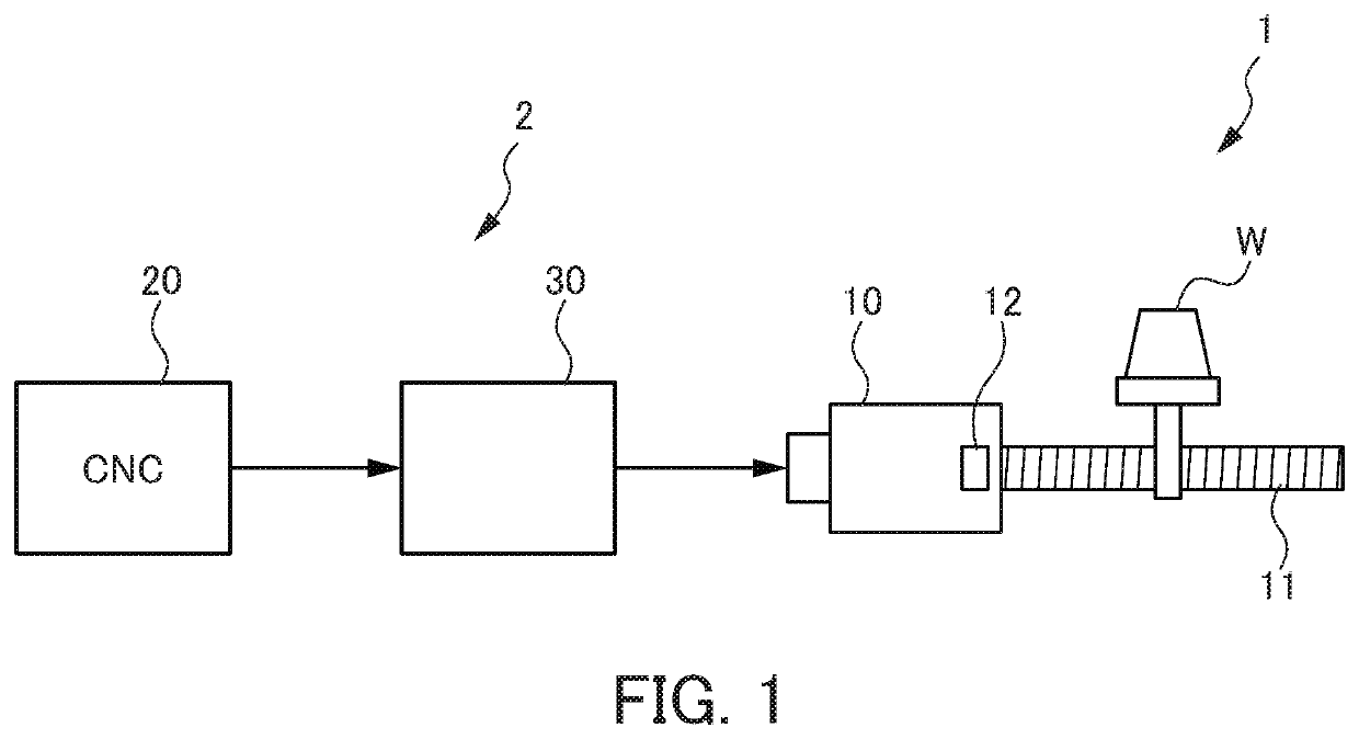
[0028]FIG. 1 is a diagram schematically illustrating a machine tool 1 to which a controller according to an embodiment of the present invention is applied. First, an example of a configuration of the machine tool 1 will be described. The machine tool 1 illustrated in FIG. 1 is a machining device that machines a work (a driven body) W into a desired shape.

[0029]The machine tool 1 of the present embodiment includes a controller 2 including a numerical controller 20 and a servo controller 30, a motor 10 controlled by the controller 2, and a feed shaft (a transmission mechanism) 11 that moves the work W using the driving force of the motor 10.

[0030]The numerical controller 20 is a computerized numerical control (CNC) and performs various processing of controlling the machine tool 1. The servo controller 30 controls the driving of the motor 10 based on commands from the num...


PUM


Abstract

A controller of a motor includes: an acceleration / deceleration time constant storing unit that stores an acceleration / deceleration time constant; a position command creating unit that creates a position command value based on the acceleration / deceleration time constant; a position detection unit that detects a rotation position of the motor; a speed command creating unit that creates a speed command for the motor on the basis of the position command value and a position detection value detected by the position detection unit; an ideal response computing unit that computes an ideal response from the position command value; and a response comparing unit that compares the ideal response with an actual response detected by the position detection unit. The response comparing unit changes the acceleration / deceleration time constant stored in the acceleration / deceleration time constant storing unit when it is determined that the ideal response does not match the actual response.

Description

[0001]This application is based on and claims the benefit of priority from Japanese Patent Application No. 2017-116582, filed on 14 Jun. 2017, the content of which is incorporated herein by reference.BACKGROUND OF THE INVENTIONField of the Invention[0002]The present invention relates to a controller of a motor that drives a driven body.Related Art[0003]Conventionally, Patent Documents 1 to 4 disclose techniques related to a controller for controlling a motor to operate a driven body.[0004]Patent Document 1 discloses a technique of gradually changing parameters until the difference between the command and the feedback becomes smaller than an allowable value in cases where the optimal value of the servo parameter has changed due to aging. In Patent Document 1, in cases where vibration is likely to occur in the actual response or where the tracking ability of the control is low, the acceleration is gradually reduced, and the time constant is increased until the positional deviation fal...

Claims


Application Information

Patent Timeline
Patent Type & Authority Patents(United States)
IPC IPC(8): G05B19/41H02P23/14H02P6/22B41J29/38G05B19/416B41J19/20
CPCG05B19/416B41J19/202B41J29/38G05B2219/37388G05B2219/43006H02P6/22H02P23/14Y02P90/02
Inventor IIJIMA, KAZUNORI
Owner FANUC LTD
Why Eureka
Try Eureka