
Electronic component cooling apparatus

a technology of electronic components and cooling apparatuses, which is applied in the direction of domestic cooling apparatus, semiconductor/solid-state device details, instruments, etc., can solve the problems of undesirable flow of cooling air generated by electric fans, and achieve the effect of reducing cross-sectional area, avoiding the reduction of cooling performance, and enhancing air tightness

Active Publication Date: 2009-05-05
SANYO DENKI CO LTD +1
View PDF19 Cites 37 Cited by
  • Summary
  • Abstract
  • Description
  • Claims
  • Application Information

AI Technical Summary

Benefits of technology

This solution provides effective cooling performance without increasing the size of the heat sink, reduces the overall size of the cooling apparatus, and enhances maintenance accessibility while preventing coolant degradation and noise interference.

Problems solved by technology

In making the most of the function of the radiator to cool the coolant, an idea of putting in front of the heat-radiating portion of the radiator an object that hinders the flow of cooling air generated by the electric fan is considered undesirable by a person skilled in the art.

Method used


Image

  • Electronic component cooling apparatus
  • Electronic component cooling apparatus
  • Electronic component cooling apparatus

Examples


Embodiment Construction

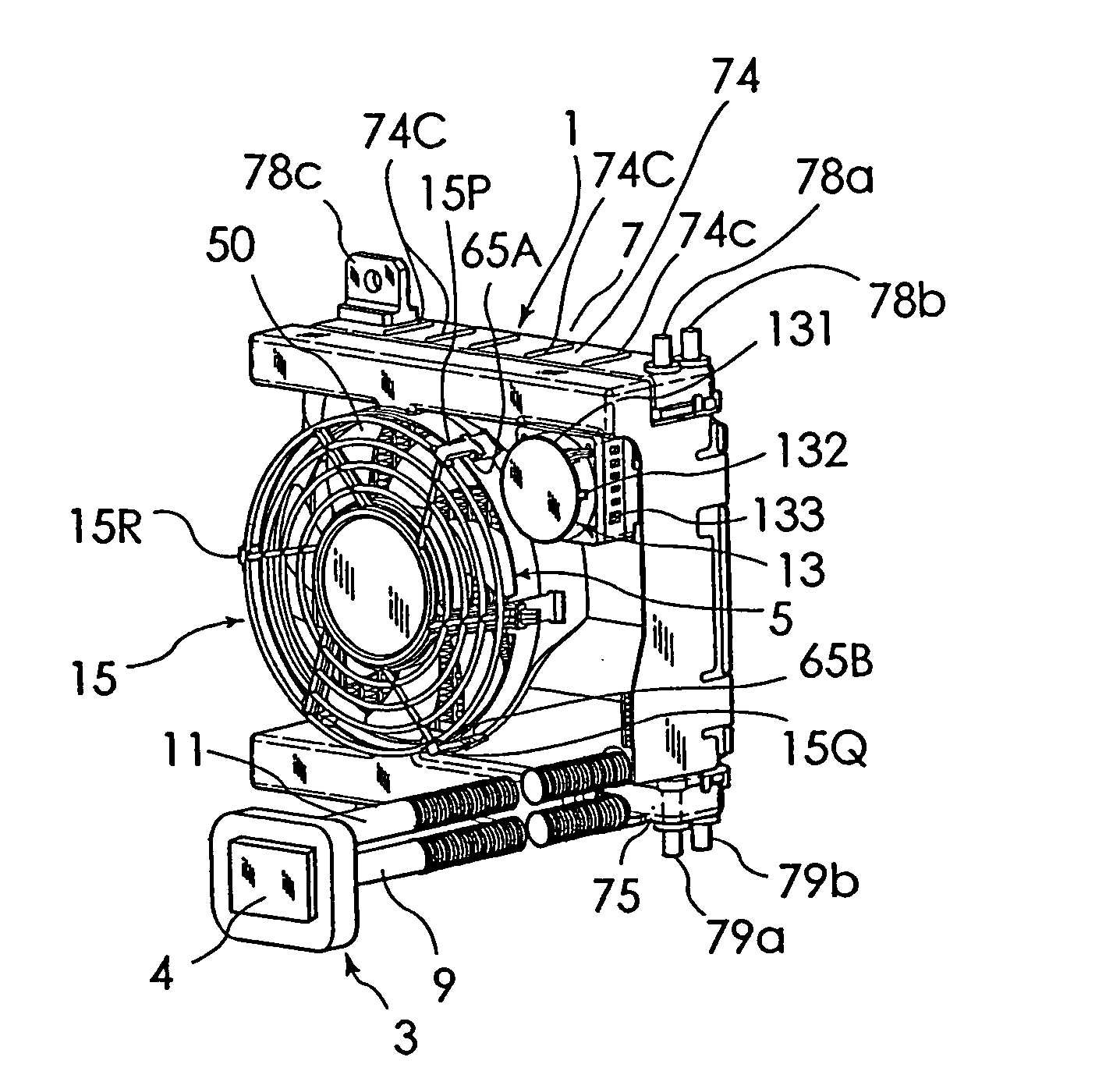
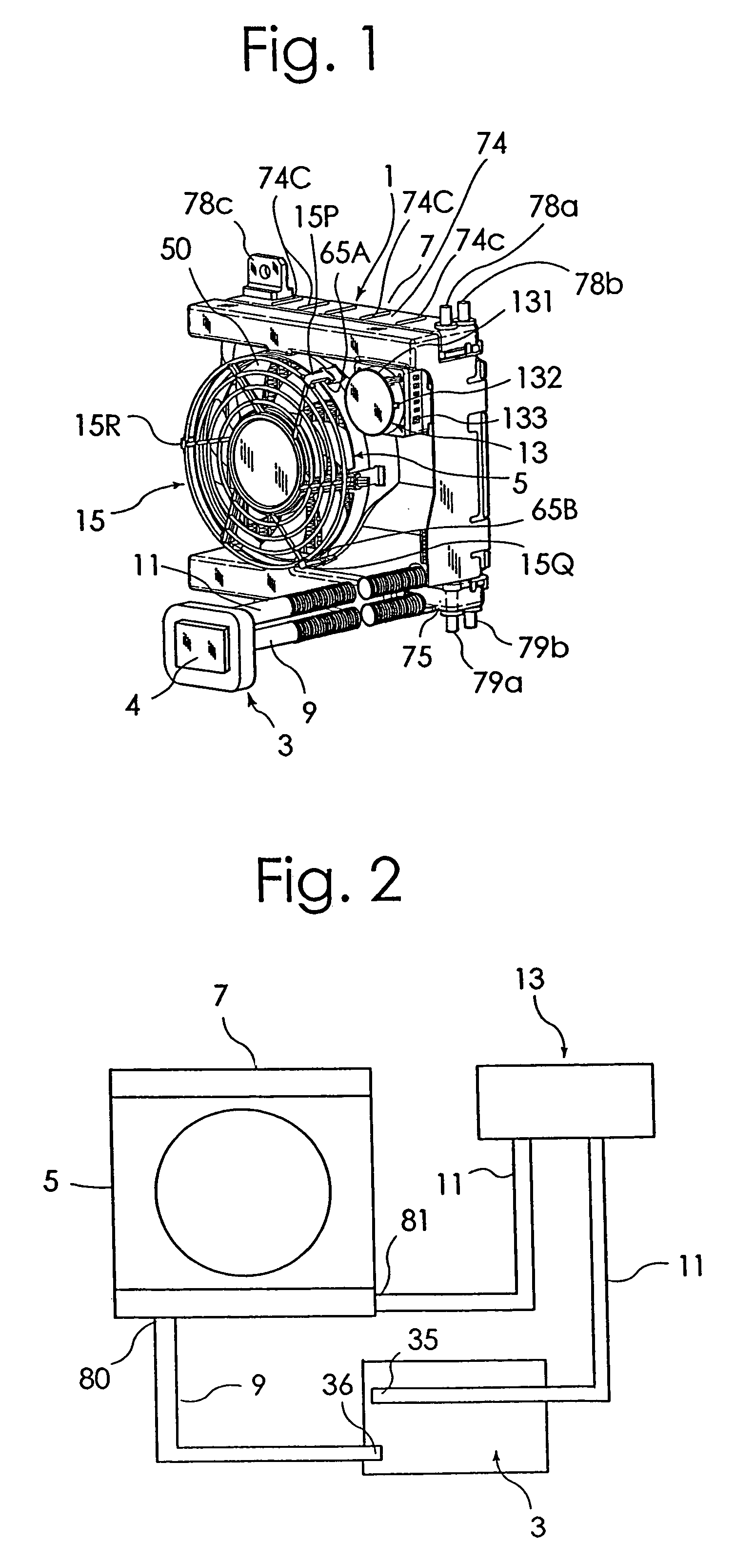
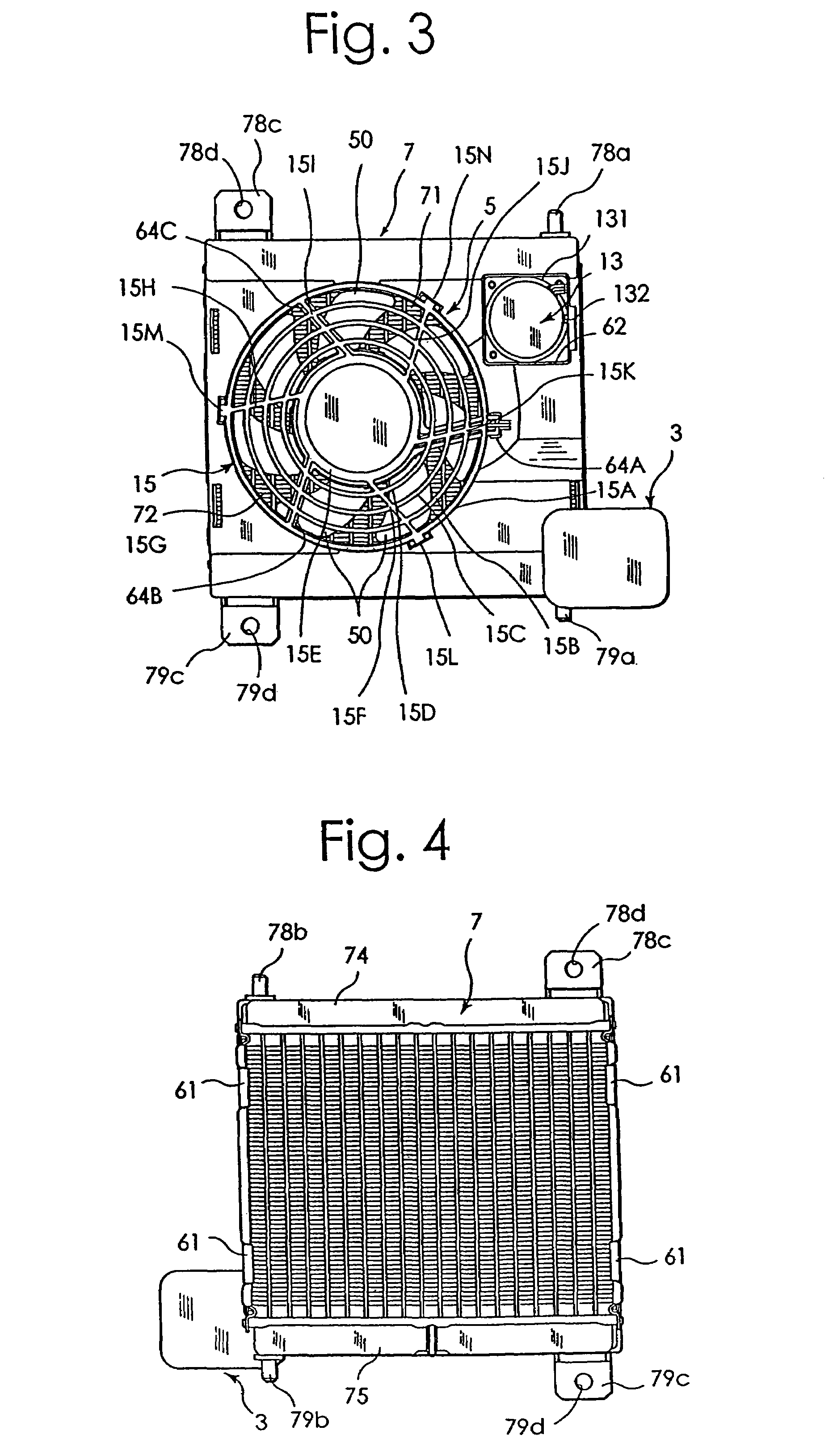
[0085]One embodiment of an electronic component cooling apparatus according to this invention will be described in detail by referring to the accompanying drawings. FIG. 1 is a perspective view of one example embodiment of an electronic component cooling apparatus 1 according to this invention. FIG. 2 is a block diagram showing flow paths in this embodiment. FIG. 3 to FIG. 8 are a front view, a rear view, a right side view, a left side view, a plan view and a bottom view of this embodiment. FIG. 9A is a front view of an electric fan 5 and FIG. 9B is a rear view of the same. FIG. 11 and FIG. 12 are a front view and a right side view, respectively, of a radiator.

[0086]As shown in FIG. 1 to FIG. 8, this electronic component cooling apparatus 1 includes a water-cooled heat sink 3 having a coolant path therein; a radiator 7 cooled by the electric fan 5; and an electric pump 13 to apply a moving energy to a coolant to circulate the coolant between the heat sink 3 and the radiator 7. As de...


PUM


Abstract

A small water-cooling type electronic component cooling apparatus is provided. The electronic component cooling apparatus comprises a so-called water-cooling heat sink 3, a radiator 7 cooled by an electric fan 5, first and second coolant paths 9, 11 for circulating a coolant between the heat sink 3 and the radiator 7, and an electric pump 13 to supply a moving energy to the coolant. The electric pump 13 is arranged at a position facing the heat-radiating portion of the radiator 7.

Description

FIELD OF THE INVENTION[0001]The present invention relates to an electronic component cooling apparatus to forcibly cool electronic components such as microcomputers and also to an electric pump and a heat sink both used in the electronic component cooling apparatus.DESCRIPTION OF THE RELATED ART[0002]Most of conventional electronic component cooling apparatus, as disclosed in U.S. Pat. No. 5,519,574, comprise a combination of a heat sink and an electric fan. The heat sink has a plurality of radiation fins formed on a surface of a base plate, and the electric fan is adapted to forcibly air-cool the surfaces of the radiation fins and the base plate.[0003]As the amount of heat produced in electronic components increases, a problem arises that simply air-cooling the heat sink cannot sufficiently cool the electronic components.[0004]An object of the present invention is to provide an electronic component cooling apparatus capable of sufficiently water-cooling electronic components that p...

Claims


Application Information

Patent Timeline
Patent Type & Authority Patents(United States)
IPC IPC(8): F28F7/00F28D15/00H05K7/20F25D9/00F28D1/053H01L23/473
CPCF28D1/05375F28D2021/0031H01L23/473H01L2924/0002H01L2924/00
Inventor IIJIMA, MASAYUKIIKEDA, TOMOAKIMIYAZAWA, MASASHIUENO, KOUJIGWIN, PAUL J.LONG, BRIAN J.DAVISON, PETER A.KONSTAD, ROLF A.
Owner SANYO DENKI CO LTD
Learn More