Electrical probe for microsurgery

a micro-surgery and electric probe technology, applied in the field of micro-surgery electric probes, can solve the problems of increasing the stress and risk of patents, unfavorable tissue damage, and the performance of the operation itself, and achieves the effects of simple operation, low cost, and easy and safe handling

Inactive Publication Date: 2009-05-05
CARL ZEISS MEDITEC AG
View PDF16 Cites 31 Cited by
  • Summary
  • Abstract
  • Description
  • Claims
  • Application Information

AI Technical Summary

Benefits of technology

[0009]It is the primary object of the invention to develop an electric probe for microsurgery in such a way that the probe is constructed in a simple manner, can be produced inexpensively, is easy and safe to handle, and at the same time can be used for multiple functions as an illuminated intraocular probe.

Problems solved by technology

When using an electrosurgical probe in surgical operations on the eye, it is problematic to ensure adequate illumination of the interior of the eye or of the fundus of the eye so that illumination is often used in addition to the surgical implement and is guided in through a second puncture.
This makes the performance of the operation itself more complicated and also increases stress on and risk to the patent.
Another great problem in intraocular treatments of the eye is that currently used cutting implements produce relatively large incisions and the surgeon must move these cutting implements relative to the tissue causing additional tensile and compressive stresses which can lead to unwanted damage to the tissue.
Another problem is intraocular illumination.
Another problem in intraocular treatment of the eye consists in that it is often necessary to detach membranes from one another intraocularly.
The probe tip itself presents a considerable source of interference in that, on one hand, the electrode tip, when introduced frontally, makes it difficult to carry out lateral ablation between the membrane and retina and, on the other hand, unwanted liquid currents occur that are directed away from the tip.
The strength of the currents and the effective depth of the probe shape depend on the electrical energy supplied, so that a destructive action occurs in axial direction and can result in damage to blood vessels or blood-conducting surface capillaries.

Method used


Image

  • Electrical probe for microsurgery
  • Electrical probe for microsurgery
  • Electrical probe for microsurgery

Examples


Embodiment Construction

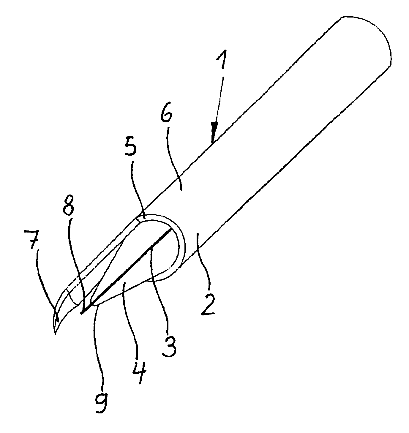
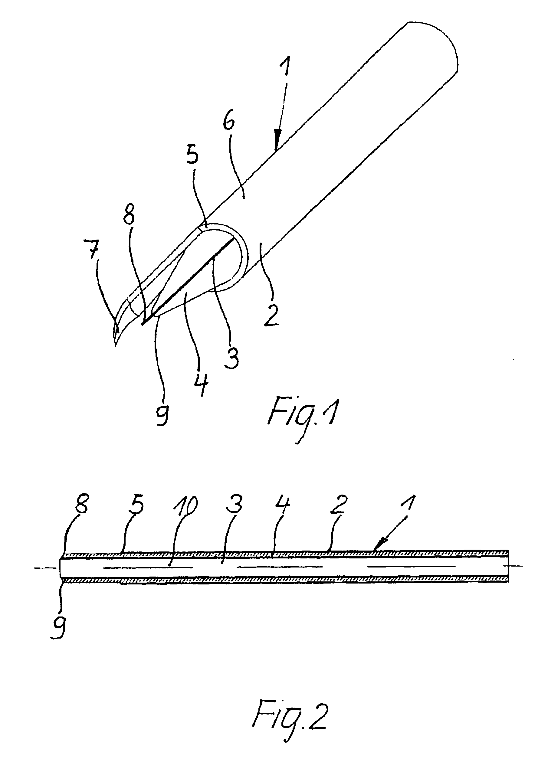
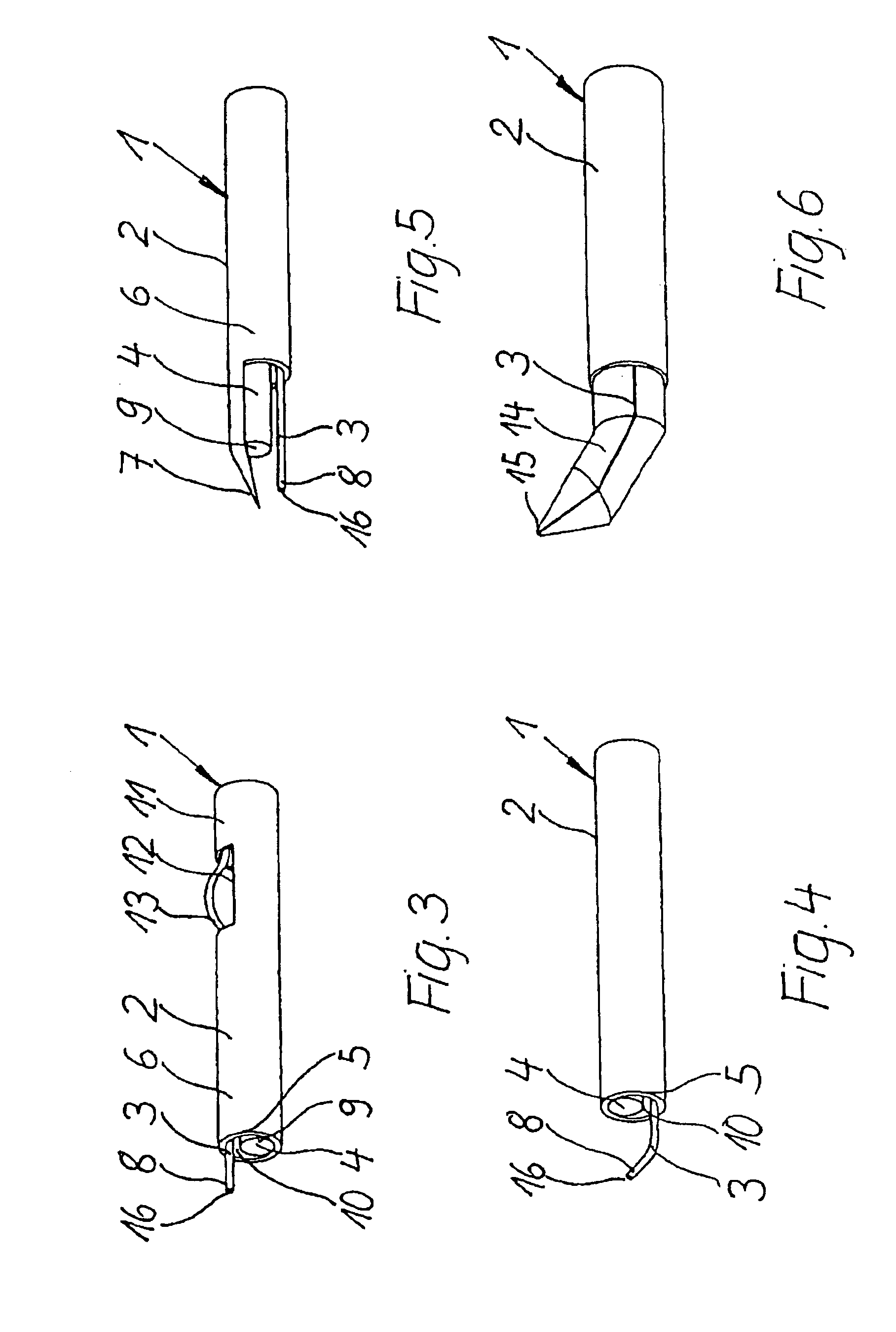
[0040]The illuminated intraocular electric probe 1 shown in FIG. 1 comprises a bare metal or partially insulated outer electrode 2 shaped as a hollow cylinder and an electrically conductive, axially insulated inner electrode 3 arranged coaxial to the outer electrode 2. The inner electrode 3 which is provided as a coated wire is constructed within the μm range. A light guide 4 enveloping the inner electrode 3 is arranged between the outer electrode 2 and the inner electrode 3, is constructed as a hollow cylinder and serves to conduct light and as insulate between the outer electrode 2 and inner electrode 3, and is provided, e.g., in the form of a glass rod or a glass capillary 14 which encloses the inner electrode and, at the same time, insulates it from the outer electrode and which is connected when working with the electric probe 1 to a light-generating unit, not shown in more detail.

[0041]In the first embodiment example of the electric probe 1 shown in FIG. 1, the inner electrode...


PUM


Abstract

In order to develop an electric probe for microsurgery, which is provided in particular in ophthalmology for intraocular treatments of the eye, in such a way that the probe is constructed in a simple manner, can be produced inexpensively, is easy and safe to handle, and at the same time can be used for multiple functions as an illuminated intraocular probe, it is suggested that the electric probe comprises an outer electrode, an inner electrode and a light guide. The inner electrode has a contoured electrode end face and projects out over a front end of the light guide or is embedded in the light guide so as to terminate with it. When the electrodes and light guide are constructed cylindrically, the hollow space remaining between the electrodes and the light guide is provided as a suction channel for sucking out tissue particles, and in various embodiment forms, including an embodiment as an illuminating endoprobe, the electric probe is connected to an operating and controlling device by which pre.-defined, changeable parameter sets which are adapted depending on the probe characteristics can be adjusted and retrieved.

Description

CROSS-REFERENCE TO RELATED APPLICATIONS[0001]This application claims priority of German Application No. 10 2004 017 744.9 filed Apr. 7, 2004 and German Application No. 10 2005 013 714.8, filed Mar. 24, 2005, the complete disclosures of which are hereby incorporated by reference.BACKGROUND OF THE INVENTION[0002]a) Field of the Invention[0003]The invention is directed to an electric probe for microsurgery which is provided in particular in ophthalmology for intraocular treatments of the eye, comprising two electrodes which are arranged coaxial to one another, a light guide which is formed as an insulator preferably being arranged therebetween, wherein the inner electrode and the outer electrode have means for connecting to an operating and controlling device.[0004]b) Description of the Related Art[0005]The use of probes of the kind mentioned above in eye surgery for electrosurgical cutting, ablation or coagulation of tissue is known. When using an electrosurgical probe in surgical ope...

Claims


Application Information

Patent Timeline
Patent Type & Authority Patents(United States)
IPC IPC(8): A61B18/18A61B1/06A61B18/14A61B19/00A61F9/007
CPCA61B18/1402A61F9/00736A61B2019/5206A61B2218/007A61F9/0079A61B2090/306
Inventor DUBNACK, STEFFENPREUSS, DIRK
Owner CARL ZEISS MEDITEC AG
Why Eureka
Try Eureka