
Method of manufacturing complementary diodes

a manufacturing method and diode technology, applied in the field of radio frequency identification and electronic article surveillance (eas) tags and sensors, can solve the problems of difficult and/or expensive implementation of convenient diode fabrication processes, diode-connected transistors may suffer from a potential drawback, and the process of transistors (tfts) may not be stable enough to achieve the effect of improving the stability of the forward voltage drop

Active Publication Date: 2009-05-05
ENSURGE MICROPOWER ASA
View PDF10 Cites 22 Cited by
  • Summary
  • Abstract
  • Description
  • Claims
  • Application Information

AI Technical Summary

Benefits of technology

"The present invention relates to a method of making process variation-tolerant diodes and diode-connected thin film transistors (TFTs) for use in identification tags and sensors. The method involves forming patterned layers of semiconductor and insulator on a substrate, followed by a patterned metal layer. The circuit also includes complementary diodes and a clamp circuit for controlling voltage on signal transmission lines. The invention also includes an antenna and inductor for receiving and converting radio frequency signals, as well as logic for generating an identification signal. The patterned structure of the invention stabilizes the threshold voltage of the diodes and improves their performance. The technical effects of the invention include improved stability and performance of printed or laser-written diodes and TFTs for use in identification tags and sensors."

Problems solved by technology

In many simple thin film fabrication processes, convenient diode fabrication processes may be difficult and / or expensive to implement.
Diode-connected transistors may suffer from a potential drawback in thin film transistor (TFT) processes, in that the threshold voltage of TFTs in many TFT processes may shift from run to run, or from lot to lot.
As a result, diode-connected TFTs made by such processes may show some variation in forward voltage drop, and the variation at times can be unacceptably large.
This is particularly unfavorable when the diodes or diode-connected TFTs are used in reference voltage supply circuits.

Method used


Image

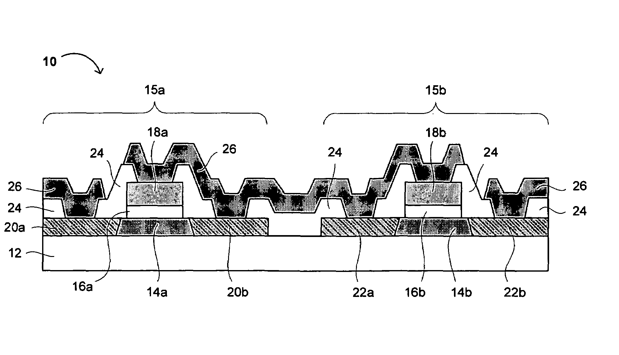
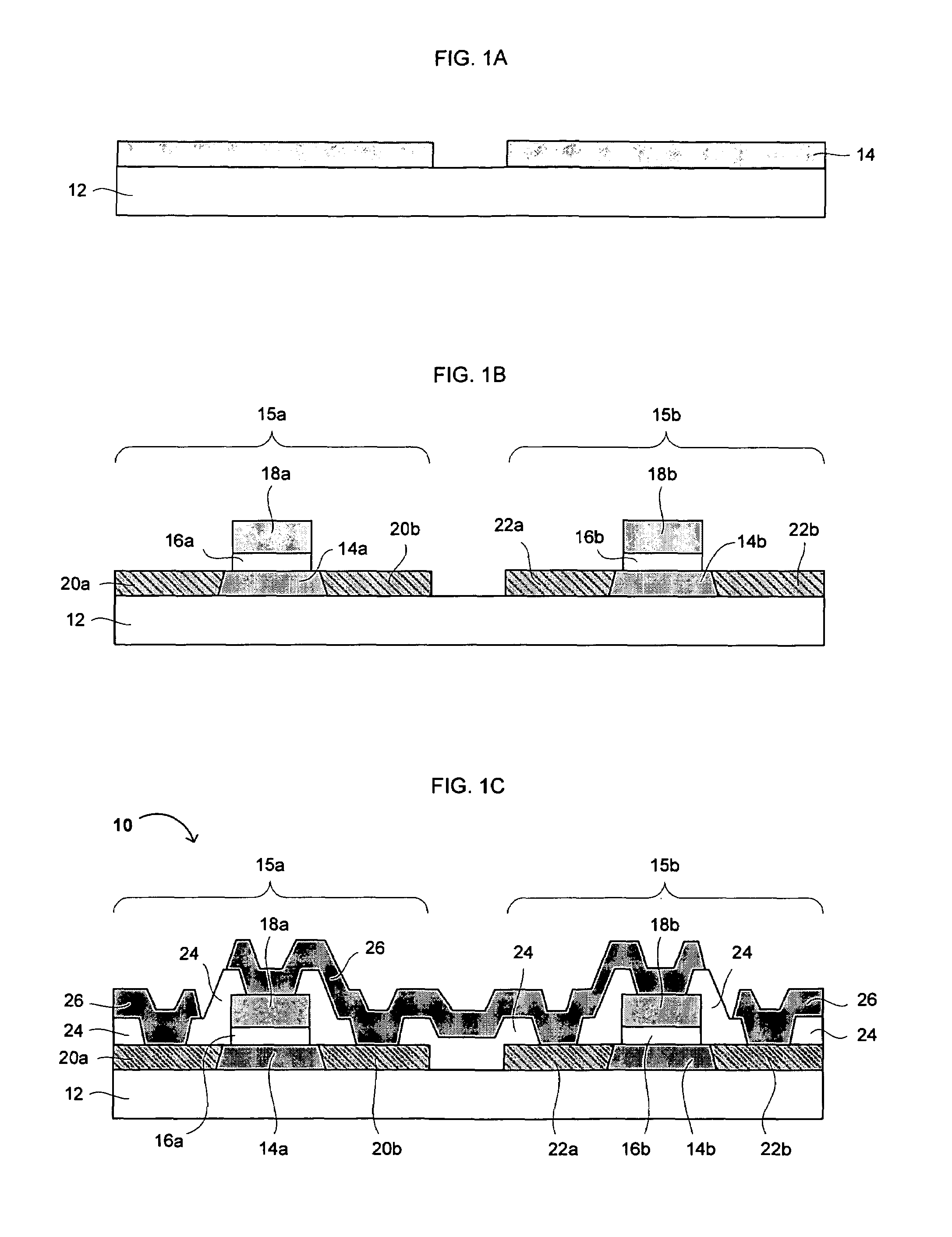
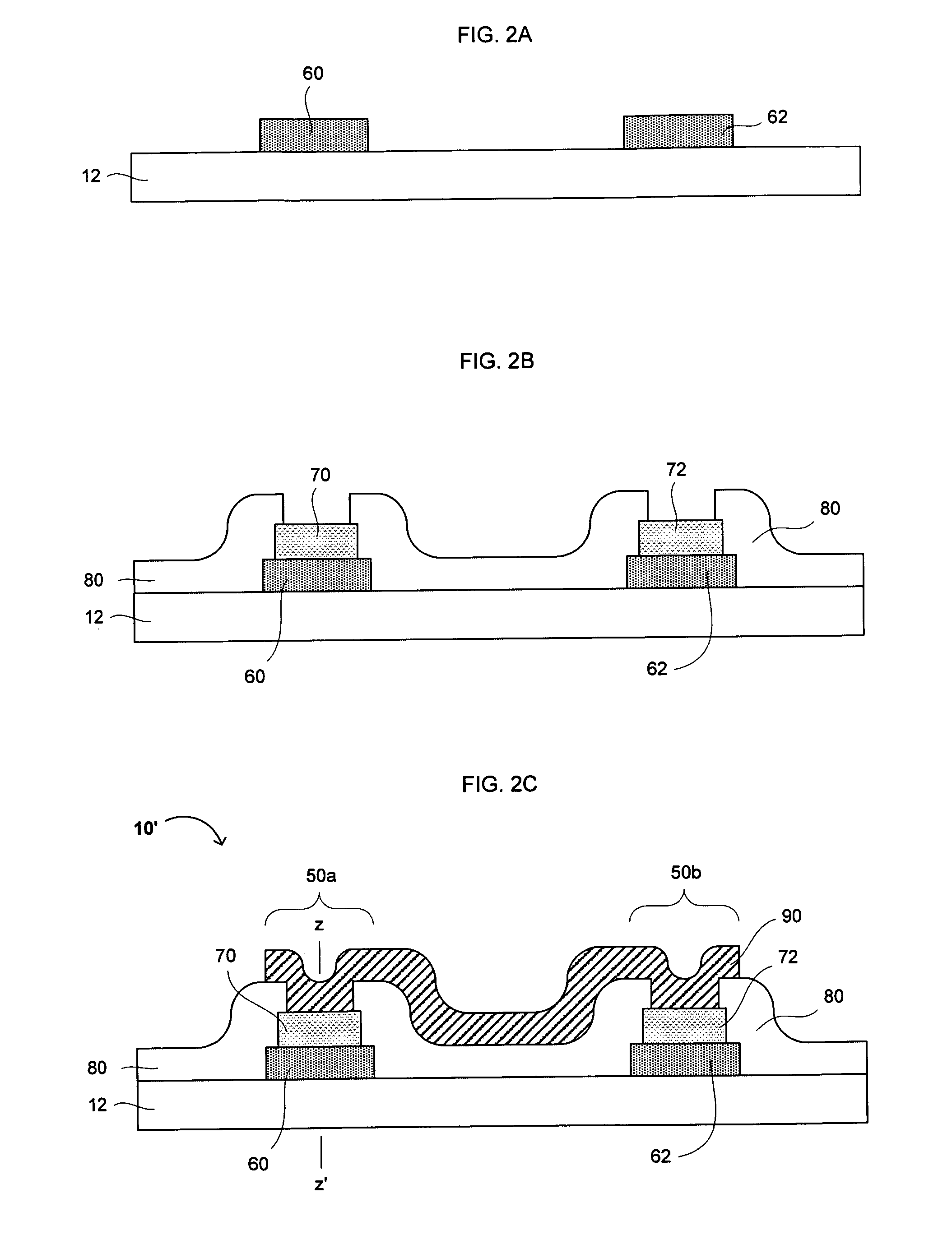
  • Method of manufacturing complementary diodes
  • Method of manufacturing complementary diodes
  • Method of manufacturing complementary diodes

Examples


Embodiment Construction

[0014]Reference will now be made in detail to the preferred embodiments of the invention, examples of which are illustrated in the accompanying drawings. While the invention will be described in conjunction with the preferred embodiments, it will be understood that they are not intended to limit the invention to these embodiments. On the contrary, the invention is intended to cover alternatives, modifications and equivalents, which may be included within the spirit and scope of the invention. Furthermore, in the following detailed description of the present invention, numerous specific details are set forth in order to provide a thorough understanding of the present invention. However, it will be readily apparent to one skilled in the art that the present invention may be practiced without these specific details. In other instances, well-known methods, procedures, components, and circuits have not been described in detail so as not to unnecessarily obscure aspects of the present inv...


PUM


Abstract

Process variation-tolerant diodes and diode-connected thin film transistors (TFTs), printed or patterned structures (e.g., circuitry) containing such diodes and TFTs, methods of making the same, and applications of the same for identification tags and sensors are disclosed. A patterned structure comprising a complementary pair of diodes or diode-connected TFTs in series can stabilize the threshold voltage (Vt) of a diode manufactured using printing or laser writing techniques. The present invention advantageously utilizes the separation between the Vt of an NMOS TFT (Vtn) and the Vt of a PMOS TFT (Vtp) to establish and / or improve stability of a forward voltage drop across a printed or laser-written diode. Further applications of the present invention relate to reference voltage generators, voltage clamp circuits, methods of controlling voltages on related or differential signal transmission lines, and RFID and EAS tags and sensors.

Description

FIELD OF THE INVENTION[0001]The present invention generally relates to the field of radio frequency identification (RFID) and electronic article surveillance (EAS) tags and sensors, and processes for manufacturing the same. In particular, the present invention relates to a process variation-tolerant diodes and diode-connected thin film transistors (TFTs), printed or patterned structures (e.g., circuitry) containing such diodes and TFTs, methods of making the same, and applications of the same for such tags and sensors.BACKGROUND OF THE INVENTION[0002]In many simple thin film fabrication processes, convenient diode fabrication processes may be difficult and / or expensive to implement. As a consequence, in many thin film processes, diode-connected transistors are used to simulate diodes in circuits. Diode-connected transistors may suffer from a potential drawback in thin film transistor (TFT) processes, in that the threshold voltage of TFTs in many TFT processes may shift from run to r...

Claims


Application Information

Patent Timeline
Patent Type & Authority Patents(United States)
IPC IPC(8): H01L21/20
CPCH01L29/86H01L27/1285H01L27/1288H01L27/1292Y10S257/91H01L29/861B82Y30/00
Inventor SUBRAMANIAN, VIVEKSMITH, PATRICK
Owner ENSURGE MICROPOWER ASA
Learn More