Step air foil

a technology of air foil and step air, which is applied in the direction of printing machines with progressive movements, instruments, etc., can solve the problems of poor flotation, disturbance or damage of coating or web, and corrugation of machine direction in the web, etc., and achieves increased air cushioning, increased draw down force, and greater support

Active Publication Date: 2009-05-12
DURR SYST INC
View PDF12 Cites 29 Cited by
  • Summary
  • Abstract
  • Description
  • Claims
  • Application Information

AI Technical Summary

Benefits of technology

[0007]The problems of the prior art have been overcome by the present invention, which provides a step air foil particularly for one-sided flotation of a running web, and a web dryer having one or more such air foils. The air foil design includes two discharge slots which allow for increased draw down force, which flattens machine direction wrinkles in a floating web. The design does not rely on a flat web to help create a cross-face velocity to draw the web to the face for proper flotation as in conventional designs. Air discharged from the primary slot is gathered into the air stream of the secondary slot and creates an increased air cushion to provide greater support to the moving web and thereby remove machine direction web wrinkles caused by higher tension in light weight webs. The two air discharge slots blow gas (air) parallel to the web over a longer area than conventional designs thereby increasing the draw down force against the web.

Problems solved by technology

Airflow instabilities near the web can induce web flutter and subsequent web contact with mechanical parts of the dryer, resulting in coating disturbance or web damage.
When floating lightweight webs under medium to high tensions, machine direction corrugations will form in the web.
This can result in poor flotation and can render the air foil ineffective.

Method used


Image

  • Step air foil
  • Step air foil
  • Step air foil

Examples


Embodiment Construction

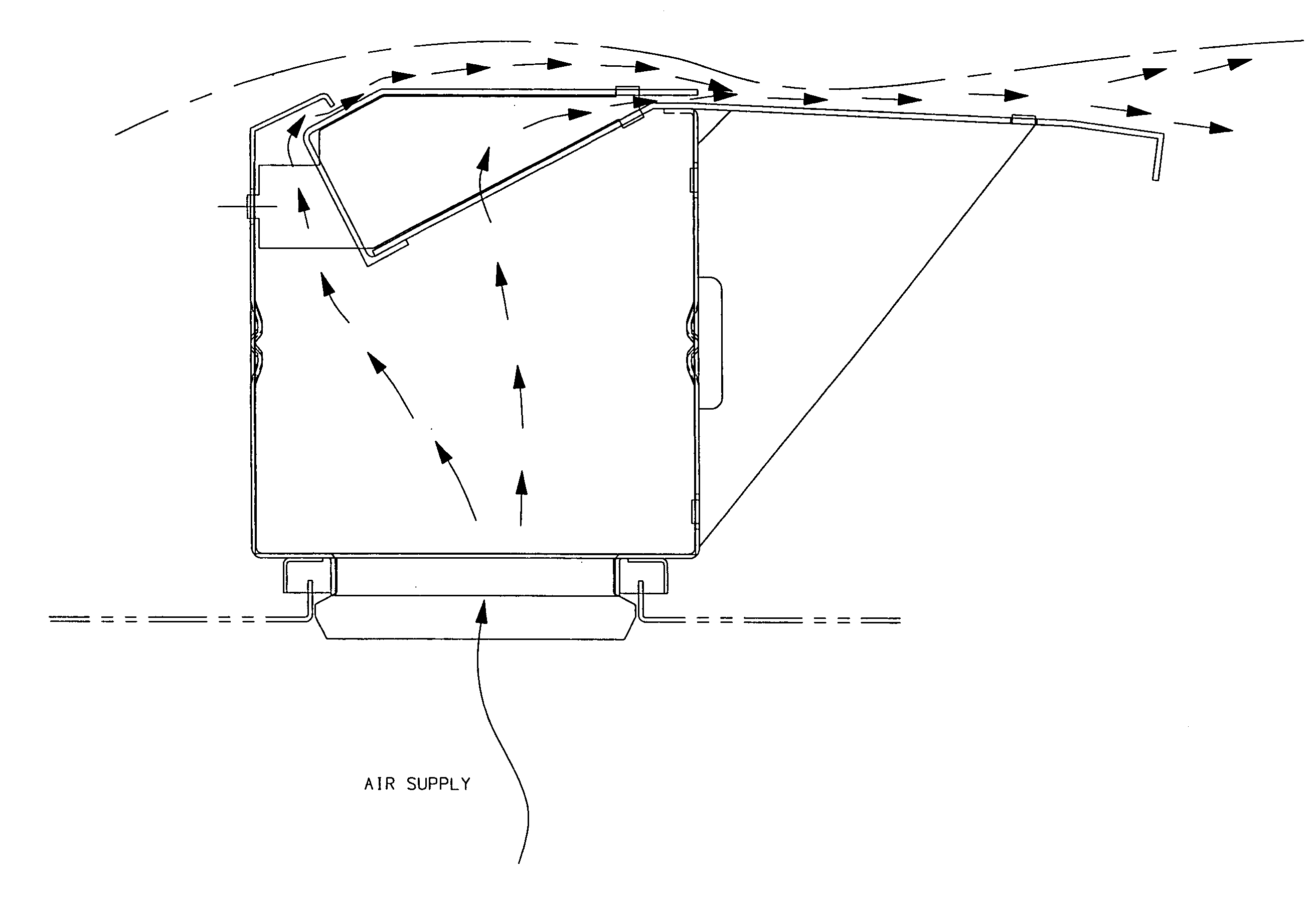
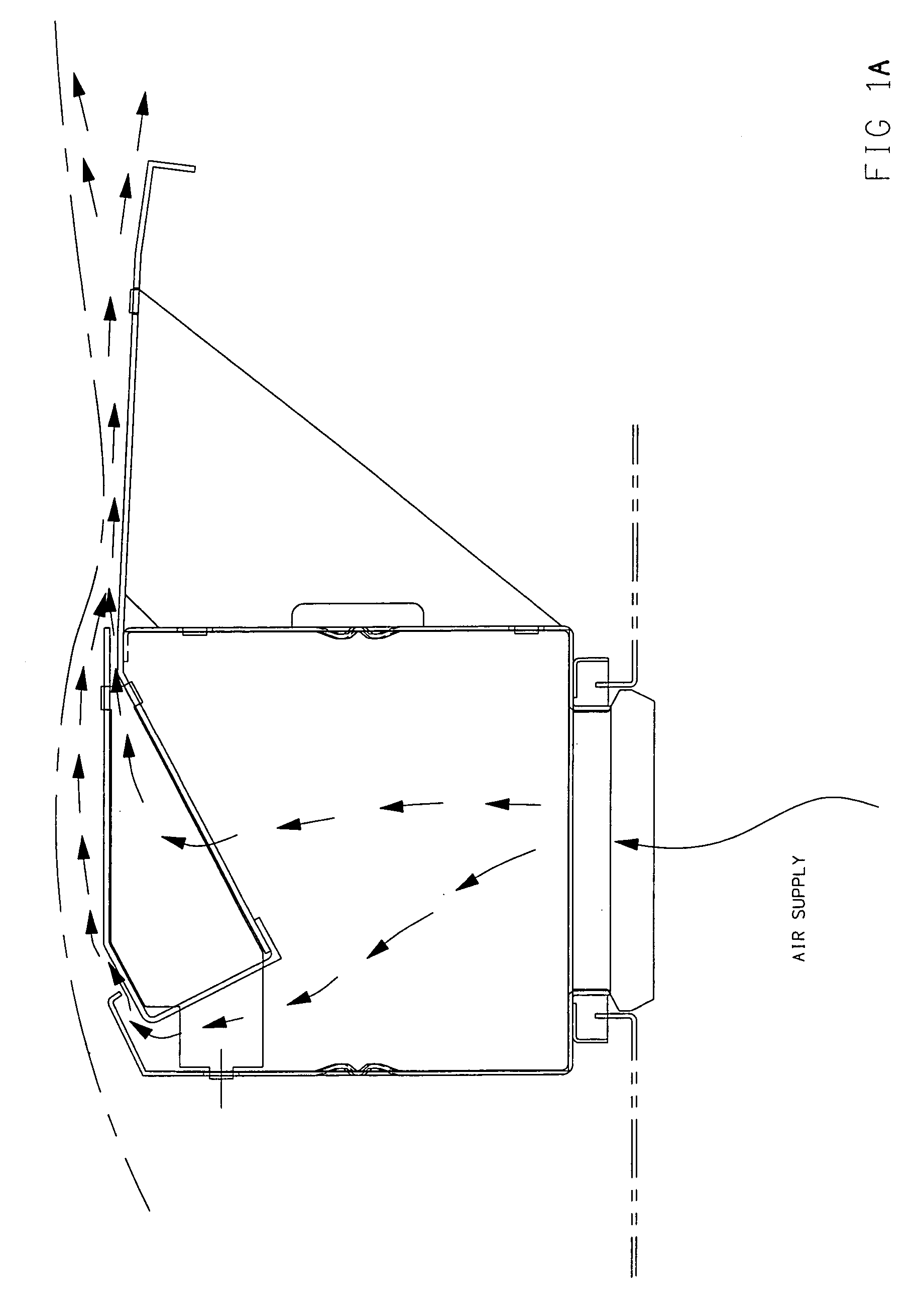
[0020]The air foil of the present invention is a unique design that incorporates a secondary slot that discharges air parallel to the web in order to maintain a constant pull down force that is independent of a flat web. It is particularly useful for one-sided flotation applications.

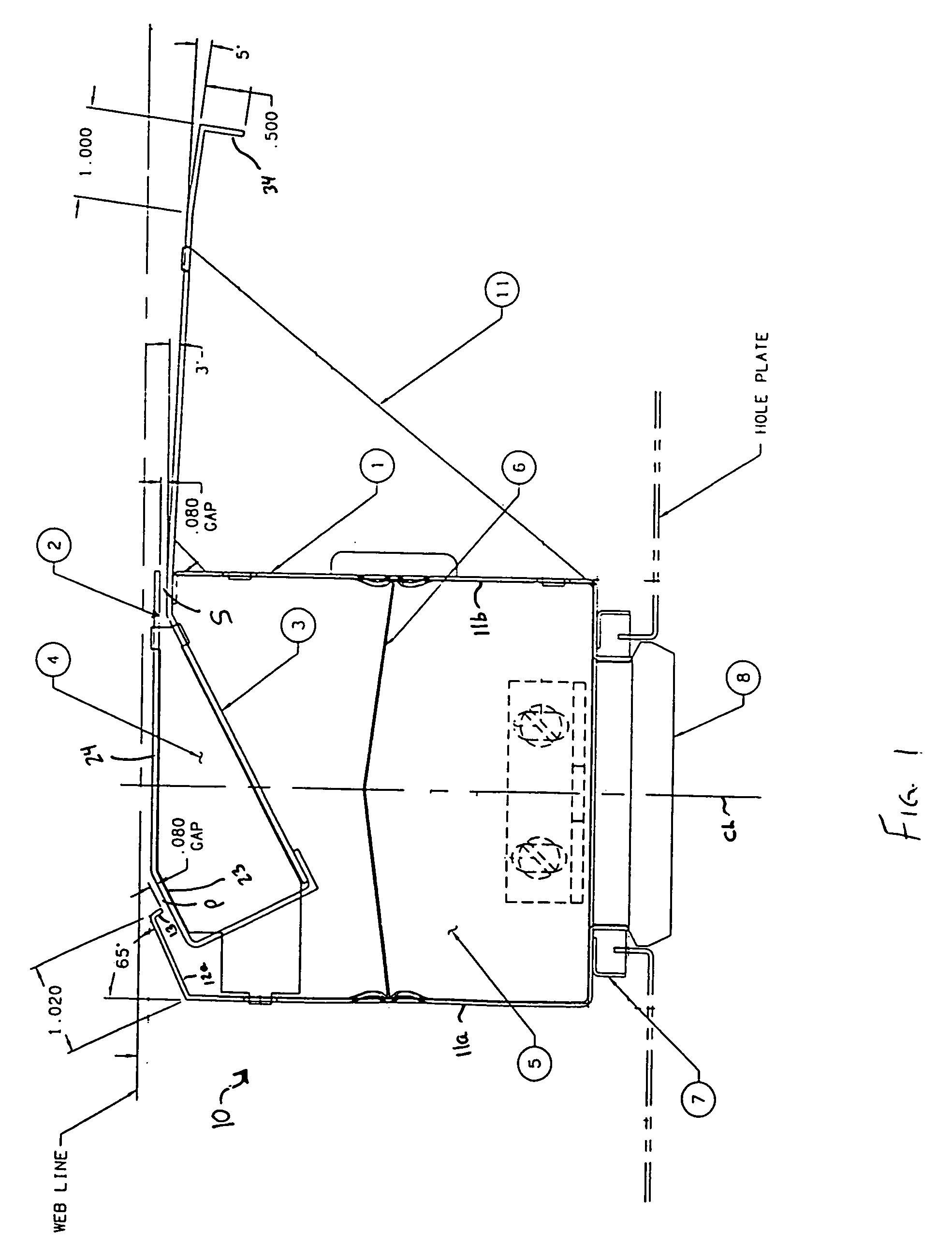
[0021]Turning now to FIG. 1, there is shown an air foil in accordance with the preferred embodiment of the invention generally at 10. The air foil 10 is defined in part by a header 1, which in the embodiment shown, is generally rectangular in cross-section except for its top portion. As seen in FIG. 2, opposite sides 11a, 11b of header 1 terminate in respective top flange portions 12a, 12b. Top flange portion 12a is angled, preferably at about 65° relative to vertical, and terminates in a bent portion 13. Top flange portion 12b extends towards opposite side 11a in a substantially horizontal fashion. The header 1 defines an interior space 5 that serves as a plenum for the gas that is received via the one ...


PUM


Abstract

Step air foil particularly for one-sided flotation of a running web, and web dryer incorporating the same. The air foil includes two discharge slots which allow for increased draw down force, which flattens machine direction wrinkles in a floating web. The air foil includes a primary discharge slot and a second discharge slot spaced from and stepped down from the primary discharge slot, a first web support surface between the primary discharge slot and the secondary discharge slot, and a second web support surface downstream of the secondary discharge slot in the direction of web travel. The air foil is in communication with an air supply which provides a supply of air that is uniformly distributed to the primary and secondary slots. Air discharged from the primary slot is gathered into the air stream of the secondary slot and creates an increased air cushion to provide greater support to the moving web and thereby remove machine direction web wrinkles caused by higher tension in light weight webs.

Description

FIELD OF THE INVENTION[0001]The present invention relates to devices for contactlessly drying and guiding traveling webs, and more particularly, an improved web air flotation device that minimizes, eliminates or removes web wrinkles.BACKGROUND OF THE INVENTION[0002]In web coating, printing and drying operations, it is often desirable that the web have contactless support, in order to avoid damage to the web itself or to the coating (such as ink) previously applied to one or more surfaces of the web. One conventional arrangement for contactlessly supporting a web during drying includes horizontal upper and lower sets of air bars between which the web travels. Hot air issuing from the air bars both dries and supports the web as it travels through the dryer.[0003]Important characteristics of any flotation system are the amount of cushioning provided by the flotation device, and the stability of the web as it passes over the device. Adequate support removes web wrinkles that typically a...

Claims


Application Information

Patent Timeline
Patent Type & Authority Patents(United States)
IPC IPC(8): F26B13/00F26B9/00F26B11/02F26B13/06F26B13/20
CPCF26B13/104F26B21/004F26B13/00F16B13/06F26B9/00
Inventor ROCHELEAU, MICHAEL O.
Owner DURR SYST INC
Why Eureka
Try Eureka