Backlight assembly having improved heat releasing structure and display device having the same
a backlight assembly and heat releasing technology, which is applied in the direction of lighting and heating equipment, instruments, display means, etc., can solve the problems of increasing the device temperature, limited ability to release thermal energy, and inability to readily release thermal energy, so as to achieve the effect of improving the heat releasing function
- Summary
- Abstract
- Description
- Claims
- Application Information
AI Technical Summary
Benefits of technology
Problems solved by technology
Method used
Image
Examples
first embodiment
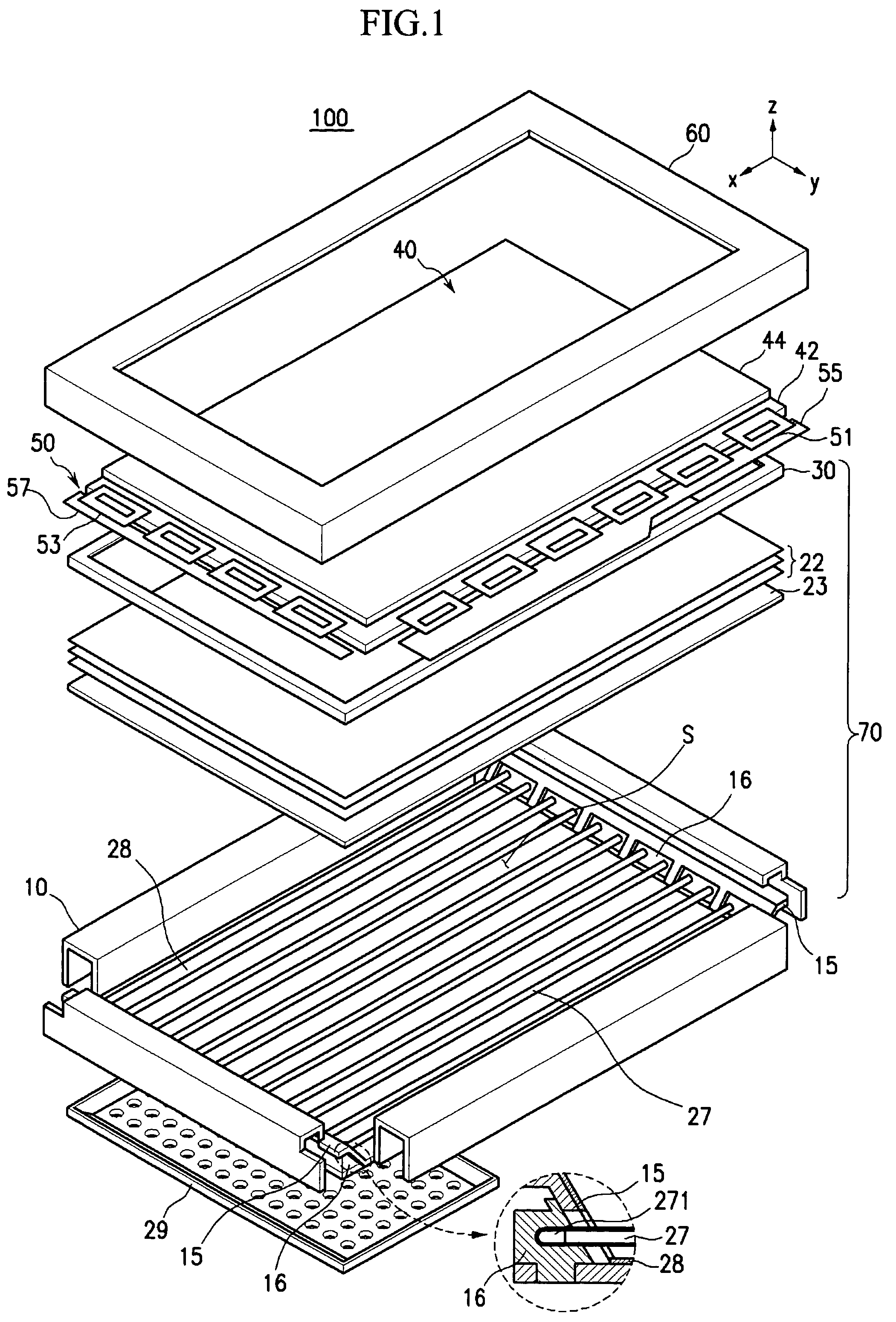
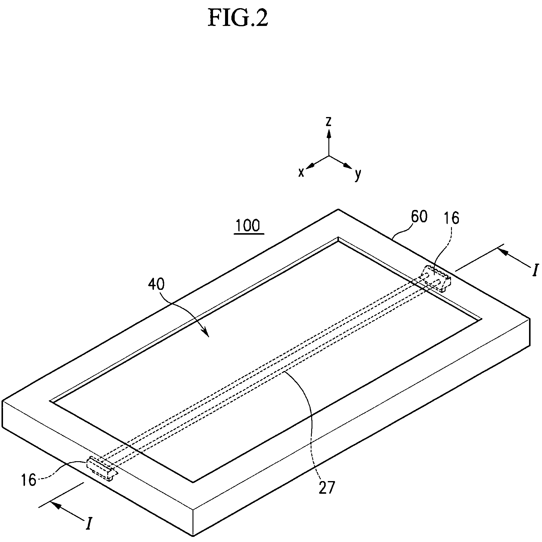
[0037]FIG. 1 shows a display device 100 having a backlight assembly 70 according to the present invention. A cross-sectional structure of a lamp holder 16 is shown in the enlarged circle of FIG. 1. The structure of the backlight assembly 70 shown in FIG. 1 is intended only to exemplify the present invention, not to limit the present invention. Therefore, the backlight assembly 70 can be modified to other structures.
[0038]The display device 100 includes a panel unit 40 displaying an image and a backlight assembly 70 supplying light to the panel unit 40. A top chassis 60 fixes the panel unit 40 onto the backlight assembly 70.
[0039]A panel unit assembly 50 includes the panel unit 40, driving IC packages 51 and 53, and printed circuit boards (PCB) 55 and 57. The panel unit assembly 50 may further include other components. A COF (Chip On Film) or TCP (Tape Carrier Package) may be used as the driving IC packages 51 and 53.
[0040]Although an LCD panel is shown as the panel unit 40 in FIG. 1...
second embodiment
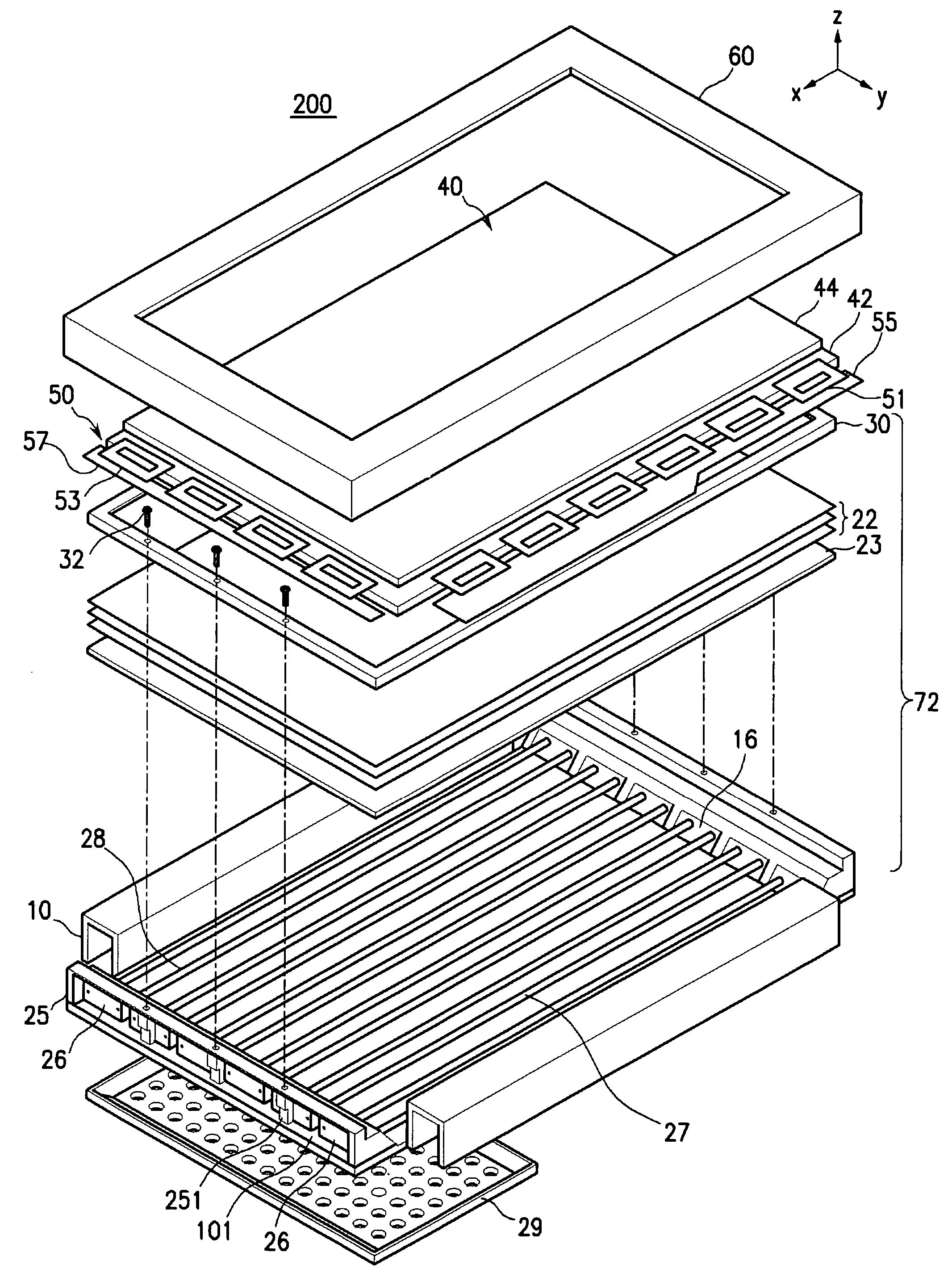
[0062]FIG. 7 shows an assembling process of the backlight assembly according to the present invention. As shown in FIG. 7, first, the lamp holders 26 are fixed to the fixing member 10 along with the reflecting sheet 28 and the lamps 27. Next, the separating member 25 is inserted and fixed below the lamp holders 26. The separating member 25 extends in the arrangement direction of the lamps 27, or the direction in which the multiple lamps 27 are arranged (shown as the Y axis direction in the coordinates in FIG. 7). In addition, the separating member 25 is opened in the longitudinal direction of the lamps 27.
[0063]FIG. 8 is a cross-sectional view taken along Line II-II of FIG. 6. As indicated by arrows in FIG. 8, the heat is externally released from the lamp holders 26. Accordingly, it is possible to efficiently remove the heat generated from the electrodes 271 of the lamps 27.
[0064]As described above, the backlight assembly according to the present invention can prevent the delivery o...
PUM
| Property | Measurement | Unit |
|---|---|---|
| angle | aaaaa | aaaaa |
| length | aaaaa | aaaaa |
| area | aaaaa | aaaaa |
Abstract
Description
Claims
Application Information
 - R&D
- Intellectual Property
- Life Sciences
- Materials
- Tech Scout
- Unparalleled Data Quality
- Higher Quality Content
- 60% Fewer Hallucinations
Browse by: Latest US Patents, China's latest patents, Technical Efficacy Thesaurus, Application Domain, Technology Topic, Popular Technical Reports.
© 2025 PatSnap. All rights reserved.Legal|Privacy policy|Modern Slavery Act Transparency Statement|Sitemap|About US| Contact US: help@patsnap.com


