Pulse width modulation method and digital analogue converter using the same

a technology of pulse width and modulation method, applied in the direction of pulse technique, digital-analog converter, instruments, etc., to achieve the effect of ensuring operation stability, expanding the dynamic range of pwm modulation, and preventing linearity deterioration

Inactive Publication Date: 2009-05-12
PANASONIC CORP
View PDF7 Cites 11 Cited by
  • Summary
  • Abstract
  • Description
  • Claims
  • Application Information

AI Technical Summary

Benefits of technology

[0035]In the PWM modulation method according to the present invention, the gradation number of the PWM modulatable digital signal can be increased than ever before, while limiting the minimum value of the pulse width and the pulse interval in consideration of the response speed of the circuit etc. which uses the output of the PWM modulation and while taking a measure for preventing the deterioration in linearity regarding the output pulse of the PWM modulation in the same way as a conventional method. Consequently, the present invention succeeds in expanding a dynamic range of the PWM modulation than that of a conventional one, while securing the operation stability of the same extent as that of the conventional method. Other objects and further features of the present invention will be apparent from the following detailed description when read in conjunctions with the accompanying drawings.

Problems solved by technology

However, when there is a limit in a response speed of a device using the PWM signal (pulse) outputted from the PWM modulator, a minimum width of each section width of the H level and the L level of the PWM signal is limited to an extent allowing this device to respond (for example, limited to 2t or more), and a stable operation of this device is secured.

Method used


Image

  • Pulse width modulation method and digital analogue converter using the same
  • Pulse width modulation method and digital analogue converter using the same
  • Pulse width modulation method and digital analogue converter using the same

Examples


first embodiment

Modification of First Embodiment

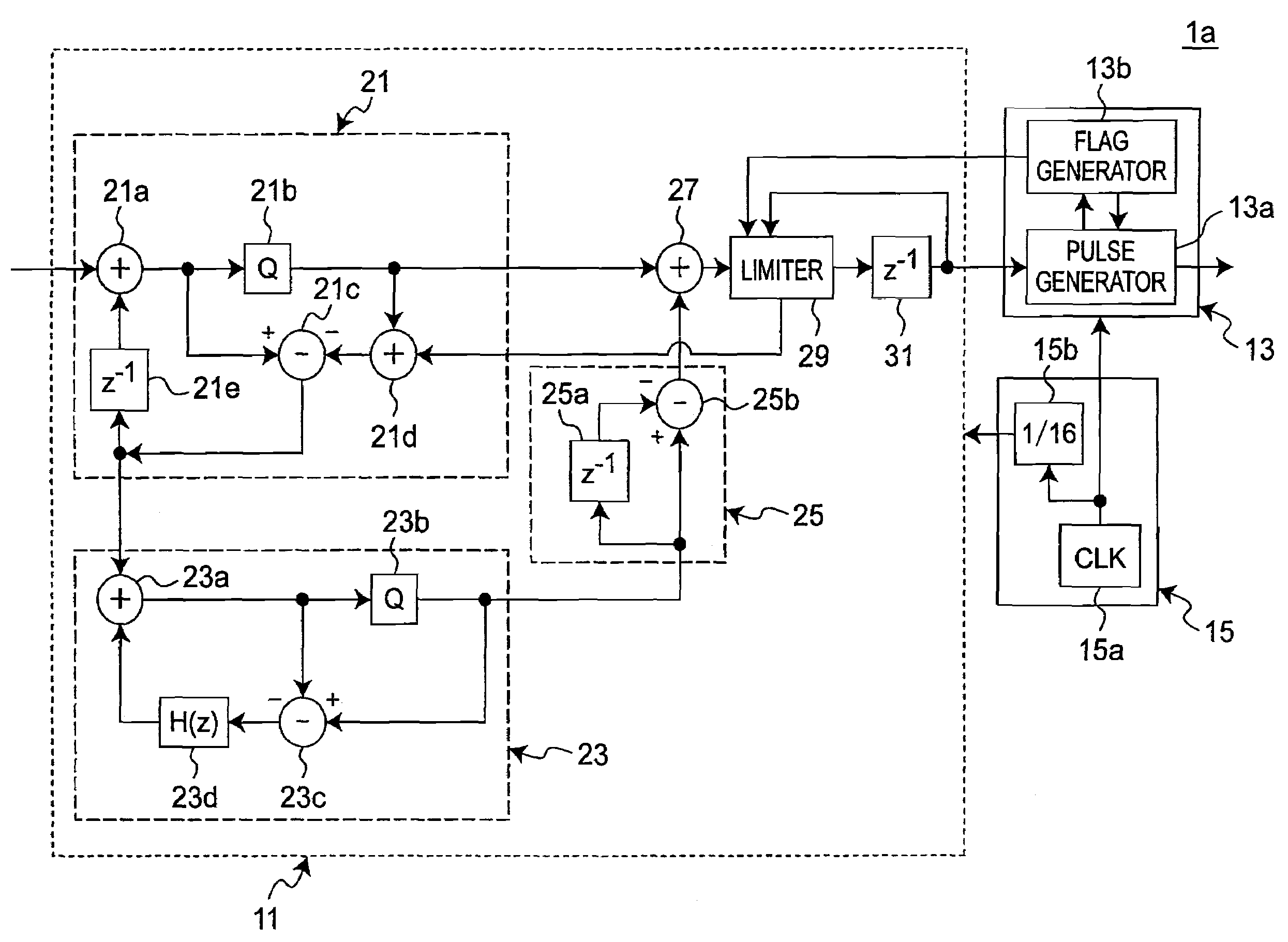
[0107]FIG. 5 is a block diagram showing an example of modification of a D / A converter 1b of the first embodiment. With reference to this figure, the modified example of the D / A converter 1b will be explained. Note that the same signs and numerals are assigned to the same constituent element as that of the D / A converter 1a, and the explanation thereof is omitted here.

[0108]The D / A converter 1b has a MASH type ΔΣ modulator 51. The MASH type ΔΣ modulator 51 includes a main loop 61, a sub-loop 23, and a differentiator 55. A significant difference from the D / A converter 1a is the point that it has a limiter 69 within the main loop 61 and before the adder 27. The limiter 69 can input the output of a delay unit 25a of the differentiator 55, and, in addition to the aforementioned operation, based on the output of the delay unit 25a further, the limiter 69 limits the output digital signal and can suitably distribute the error being occurred in the limitation t...

second embodiment

[0109]FIG. 6 is a block diagram of a digital-analogue converter (D / A converter) 1c according to a second embodiment of the present invention. The D / A converter 1c is the delta-sigma (ΔΣ) type D / A converter in the same way as the D / A converter 1a. The explanation for the same constituent element as that of the D / A converter 1a is omitted in the description about the D / A converter 1c. Also, regarding the same operation of each constituent element as that of the D / A converter 1a according to the first embodiment, the explanation thereof is simplified or omitted.

[0110]When the D / A converter 1c being compared to the D / A converter 1a according to the first embodiment, the flag generator is omitted from a PWM modulator 73 of the D / A converter 1c, and along with this omission, the input of the flag to a limiter 89 is also omitted. The D / A converter 1c according to the second embodiment corresponds to the D / A converter 1a according to the first embodiment except for the aforementioned point....

third embodiment

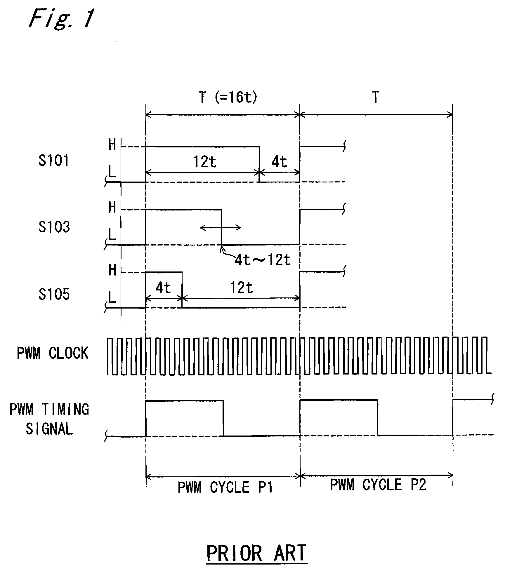
[0131]In the PWM modulation method according to a third embodiment, the D / A converter 1c having the same configuration as that of the second embodiment can be used. Therefore, explanation for the configuration of the D / A converter 1c according to the third embodiment is omitted. FIG. 9 shows examples (S31 to S34) of the PWM signal (pulse) being outputted by the pulse generator 73a of the PWM modulator 73 and the PWM clock being outputted by the clock signal generator 15 and the PWM timing signal. With reference to this figure, the PWM modulation according to this embodiment will be explained. In the same way as the first and second embodiments, the interval of PWM clocks is represented as t, and the interval of PWM timing signals is represented as 16t (where 16t=T, T is the PWM cycle).

[0132]In this embodiment, the section where the H level as the first level is outputted and the section where the L level as the second level is outputted are limited so as to have the section width of...


PUM


Abstract

In a pulse width modulation method of the present invention, a digital signal is modulated and a pulse width modulation signal is generated in a pulse width modulator by using a digital signal output unit and the pulse width modulator The pulse width modulation method includes: outputting to the pulse width modulator a first value corresponding to the input signal as a first digital signal at a first timing by the digital signal output unit; determining a limited value range based on the first value by the digital signal output unit; determining a second value corresponding to a new input signal by the digital signal output unit; judging whether or not the second value is included in the limited value range, and when the second value being judged to be included, outputting the second value to the pulse width modulator as a second digital signal, and when the second value being judged not to be included, outputting a value included in the limited value range to the pulse width modulator as the second digital signal at the second timing at which at least one cycle has elapsed from the first timing by the digital signal output unit; and modulating the pulse width of the second digital signal and generating the pulse width modulation signal, by the pulse width modulator.

Description

BACKGROUND OF THE INVENTION[0001]1. Field of the Invention[0002]The present invention relates to a pulse width modulation method, and particularly relates to a method for pulse-width modulating (PWM) a digital signal input from a digital signal output unit in a digital-analogue (D / A) converter. Also, the present invention relates to a D / A converter using this pulse width modulation method.[0003]2. Description of the Related Art[0004]In a process of converting a digital signal to an analogue signal (digital-analogue (D / A conversion)), a pulse width modulation (PWM) is widely used.[0005]In a well-known PWM method, based on the digital signal inputted to a PWM modulator in each PWM cycle, a time width of a section of a high level (H level) of a pulse (PWM signal) and a time width of a section of a low level (L level) of the pulse (PWM signal) are determined, and a profile of an output pulse is determined.[0006]FIG. 1 is a diagram exemplifying the PWM signal formed in one system of a we...

Claims


Application Information

Patent Timeline
Patent Type & Authority Patents(United States)
IPC IPC(8): H03M1/82
CPCH03M3/358H03M7/3022H03M3/506
Inventor KITAHIRA, NAOTAKETAKAYAMA, TSUYOSHI
Owner PANASONIC CORP
Why Eureka
Try Eureka