
Apparatus and methods for detection of multiple targets within radar resolution cell

a technology of radar resolution and target detection, applied in the field of frequency diverse subpulse radar systems, can solve the problems of increased risk of damage, increased cost, and underestimate the size of the threa

Inactive Publication Date: 2009-05-19
LOCKHEED MARTIN CORP
View PDF23 Cites 19 Cited by
  • Summary
  • Abstract
  • Description
  • Claims
  • Application Information

AI Technical Summary

Benefits of technology

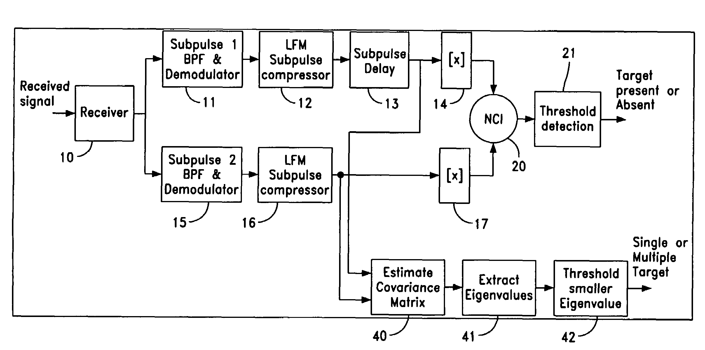
The patent describes a method for detecting multiple targets in a radar system using a frequency diverse radar waveform. The method involves processing the received echo signal in multiple channels, each responsive to one of the subpulses, and integrating both processed subpulses to detect the presence of a target. A covariance matrix is then formed from each processed subpulse and an Eigenvalue decomposition is performed on the matrix. The resulting Eigenvalues are thresholded to select those indicating a signal strength above a predetermined threshold. If multiple Eigenvalues exceed the threshold, multiple targets are determined. The technical effect of this method is improved detection of multiple targets in a radar system.

Problems solved by technology

In military radars, this can result in underestimating the size of the threat.
Hence, a greater risk of damage may result, especially in a military environment.
Such systems result in a higher cost and in some cases longer waveform dwell times. The wider bandwidth waveforms often operate on only a limited range window.
Such radars are complicated and much more expensive than conventional radar systems.
If there are multiple targets such as a squadron of aircraft flying in close formation, typical prior art radar systems will detect this condition as a single target and thus would not respond to or identify multiple targets.

Method used


Image

  • Apparatus and methods for detection of multiple targets within radar resolution cell
  • Apparatus and methods for detection of multiple targets within radar resolution cell
  • Apparatus and methods for detection of multiple targets within radar resolution cell

Examples


Embodiment Construction

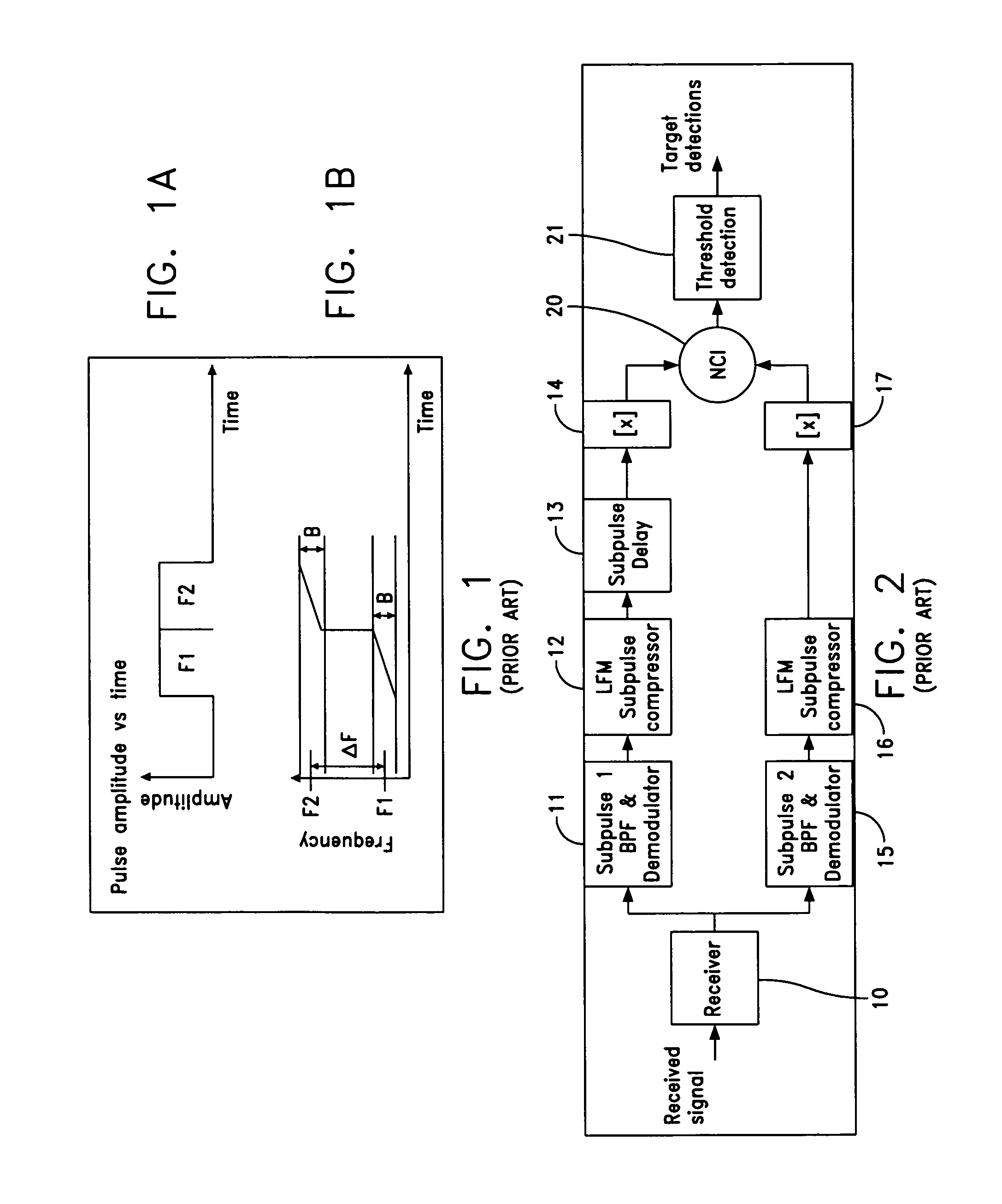
[0018]Referring now to the drawings, FIG. 1A shows a graphical representation of pulse amplitude versus time which essentially depicts pulses F1 and F2. FIG. 1A shows two contiguous subpulses but it is known that the pulses F1 and F2 may also be separated in time. FIG. 1B shows the instantaneous pulse frequency versus time which shows the frequency difference between frequencies F1 and F2 as well as showing the instantaneous frequency versus time and the bandwidth B.

[0019]Radar systems using a waveform which consists of two or more frequency diverse subpulses as shown in FIG. 1 are well known. The use of frequency diversity waveforms to improve target detectability by reducing the fluctuation loss is a well known technique. Reference is made to an article entitled “Losses for Frequency Diversity Waveforms Systems” by Ramon Nitzberg, which is published in the IEEE Transactions on Aerospace and Electronic Systems, Vol. AES-14 No. 3, May 1978. As one can see the use of multiple carrier...


PUM


Abstract

A method and apparatus is operative for multiple target detection in a radar system which employs a radar waveform of two or more frequency diverse subpulses. The apparatus adds coherent processing of the subpulse echo signals to determine the presence of multiple scattering centers within the radar resolution cell. The subpulses are coherently combined and one can then estimate the number of scattering centers by forming a sample covariance matrix between the subpulse frequency channels and then performing an Eigenvalue decomposition. The resulting Eigenvalues represent the signal strengths of the scattering centers when the associated Eigenvectors correspond to the optimal subpulse weights associated with that signal. A single strong Eigenvalue indicates a single target while two or more strong Eigenvalues or those Eigenvalues larger than the noise related Eigenvalues or a threshold, indicates the presence of multiple targets.

Description

FIELD OF INVENTION[0001]The present invention relates to frequency diverse subpulse radar systems and more particularly to a method and apparatus for detecting multiple closely spaced targets employing such a radar system.BACKGROUND[0002]The prior art is cognizant of the need to detect multiple aircraft flying in close formation. Such aircraft which fly in close formation may appear essentially as a single target to a conventional radar system. In military radars, this can result in underestimating the size of the threat. As one can ascertain, if there are multiple aircraft flying in close formation, and the radar detects this as a single aircraft, then the proper defense may not be provided. Hence, a greater risk of damage may result, especially in a military environment. One approach to addressing this problem has been to design radar systems which support wider bandwidth waveforms. Such systems result in a higher cost and in some cases longer waveform dwell times. The wider bandw...

Claims


Application Information

Patent Timeline
Patent Type & Authority Patents(United States)
IPC IPC(8): G01S13/24G01S13/46G01S13/00G01S13/44
CPCG01S13/24G01S13/30G01S13/282G01S7/41
Inventor KUHN, WALTER A.
Owner LOCKHEED MARTIN CORP
Learn More