

JTAG testing arrangement
a testing arrangement and jtag technology, applied in the field of jtag testing, can solve the problems of complex implementation of uplink interface, high implementation cost, and component defects in circuits, and achieve the effect of simplifying testing equipment and reducing the number of required hardware components
- Summary
- Abstract
- Description
- Claims
- Application Information
AI Technical Summary
Benefits of technology
Problems solved by technology
Method used
Image

Examples
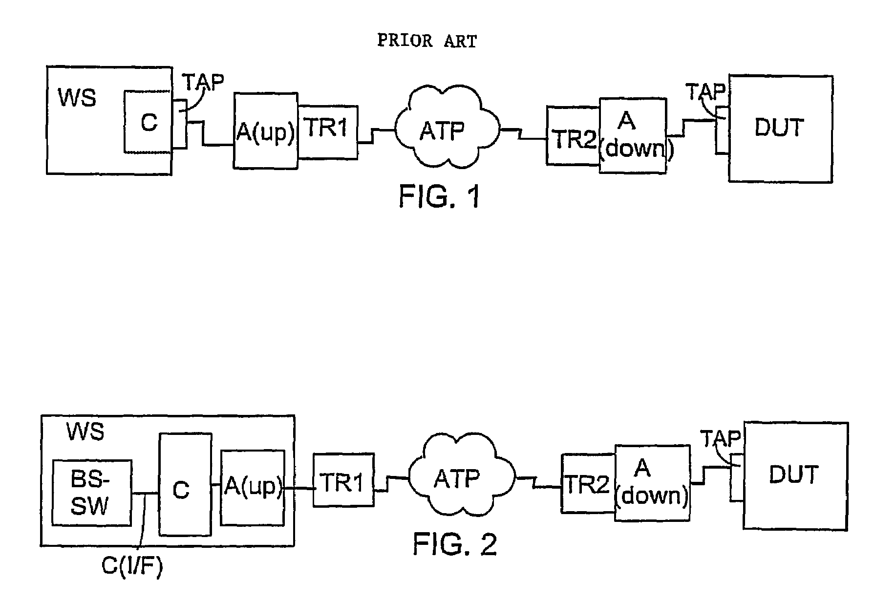
Embodiment Construction
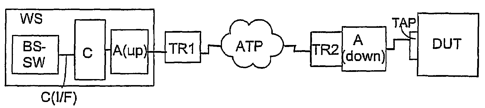
[0013]FIG. 1 shows the arrangement of the prior art described in EP 1,189,070 for testing a device under test DUT with test equipment in a JTAG controller. The testing arrangement comprises a workstation WS and a JTAG controller C connected functionally thereto. The workstation typically comprises software that controls the running of a boundary scan test performed at each time. The JTAG controller C in turn forms the JTAG test vectors used in the testing and transmits them to the TAP interface and correspondingly receives from the TAP interface the test vectors coming from the device under test DUT. At least a test mode select signal TMS and a test data input TDI are formed on the TAP interface of the JTAG controller C for transmission to the device under test DUT. On the side of the transmission path of the JTAG controller's C TAP interface, an uplink adapter A(up) is arranged to adapt the test data TDI to be transmitted and the test mode select signal TMS into the format used on ...
PUM
 Abstract
Description
Claims
Application Information