Gas-liquid impingement separators

a separator and gas liquid technology, applied in the direction of separation process, auxillary pretreatment, dispersed particle separation, etc., can solve the problems of high energy consumption, severe pressure drop, and liquid droplets that may constitute a loss of valuable reactants

Active Publication Date: 2009-05-26
ALPEK POLYESTER SA DE CV
View PDF24 Cites 8 Cited by
  • Summary
  • Abstract
  • Description
  • Claims
  • Application Information

AI Technical Summary

Problems solved by technology

However, in other processes, considerable quantities of liquid droplets may be associated with the gas phase, and in the case where the liquid droplets can later solidify, whether due strictly to a phase change or to subsequent reaction, lines and valves may be plugged and require disassembly and cleaning or replacement.
Furthermore, in many cases, the liquid droplets may constitute a loss of valuable reactants, intermediate products, or end products.
However, many of these methods, for instance chill plates, are energy intensive, and others such as packed columns exhibit a severe pressure drop as well as being prone to plugging.
In-line filters also suffer from these drawbacks.
However, such separators are generally efficient only for droplets of materials with large inertia.
Since in many cases the separator must be maintained at a specific operating temperature and thus requires considerable external insulation, such devices are relatively capital intensive.
This device is of rather complex construction, and is believed to be useable only when configured for horizontal flow due to the placement of liquid-trapping baffles and drains.
Moreover, conversion of linear flow to a swirling flow necessarily requires energy, which is manifested as a pressure drop.
Use of a rinsing liquid is undesirable in many applications.
The fishbone construction described in the '150 application is limited in that it is placed in the upstream (inlet) region of an elbow where the centerline of the elbow inlet is substantially vertical.
This limitation is significant in that the conduit system carrying the gas exiting polymerization reactors tend to be large and inflexible offering only a limited number of available conduit positions for placing the gas-liquid separator.

Method used


Image

  • Gas-liquid impingement separators
  • Gas-liquid impingement separators
  • Gas-liquid impingement separators

Examples


Embodiment Construction

)

[0037]Reference will now be made in detail to presently preferred compositions or embodiments and methods of the invention, which constitute the best modes of practicing the invention presently known to the inventors.

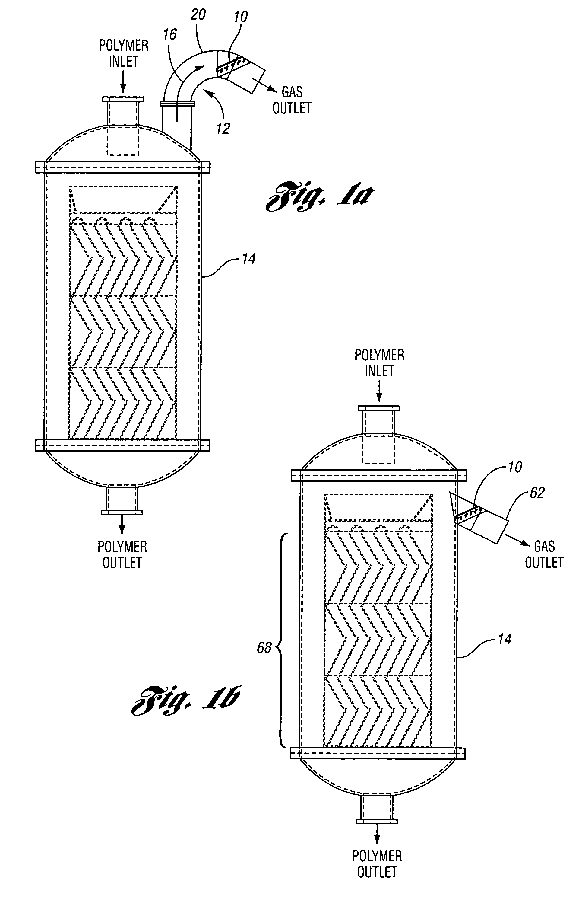
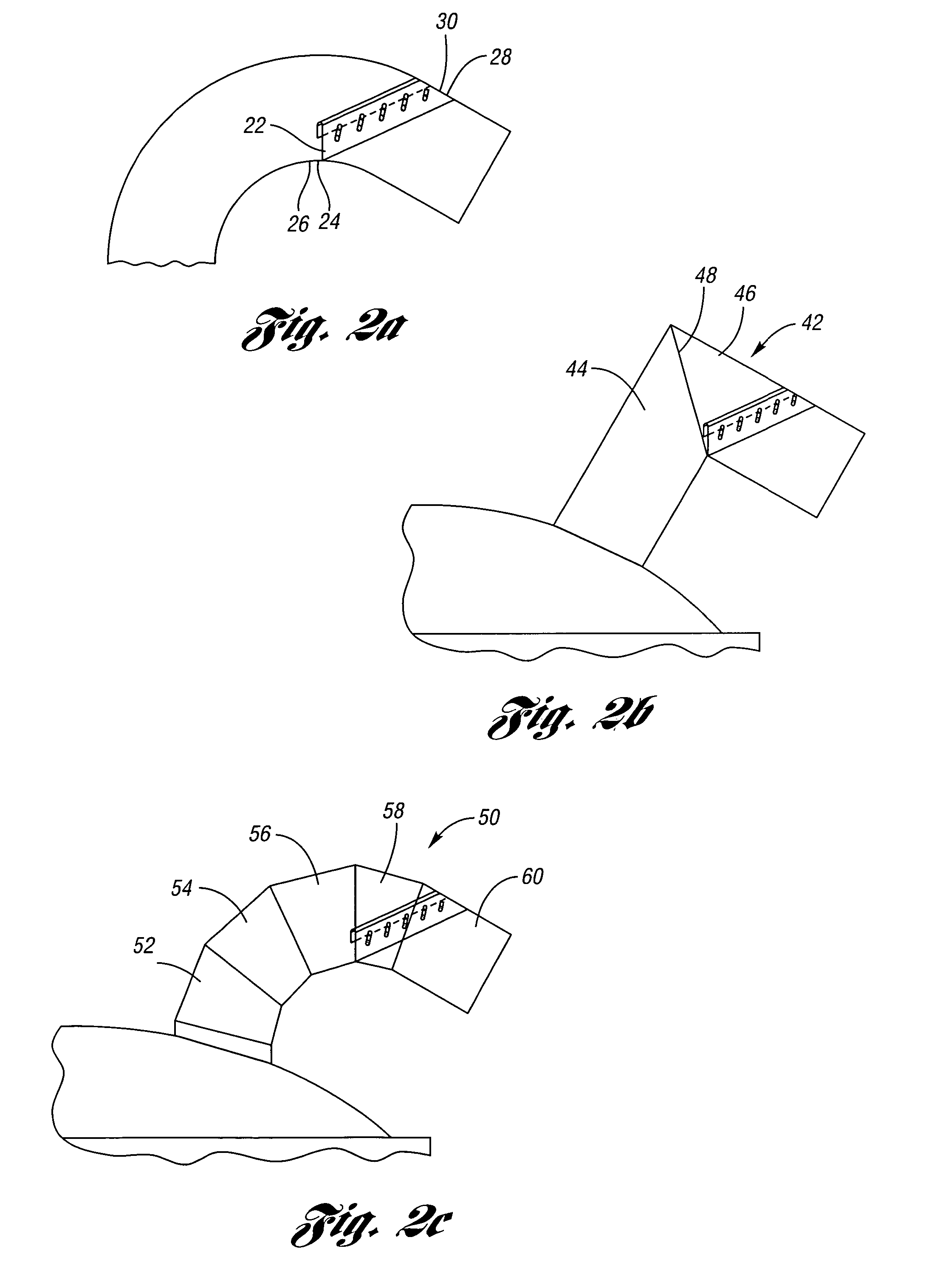
[0038]With reference to FIGS. 1A and 2A, a first embodiment of the gas-liquid separation enhancer (i.e., the gas-liquid separator) of the invention is provided. FIG. 1A provides a side-view of the separation enhancer placed within the exit region of an elbow of a reactor conduit. FIG. 2A is a magnified view of the side-view of FIG. 1A. Gas-liquid separation enhancer 10 is positionable in conduit 12 for separating liquid from a stream having gas and liquid droplets emanating from process vessel 14. Typically, conduit 12 has a circular cross-section although other shapes are possible. The stream flows through conduit 12 in flow direction 16 which leads away from process vessel 14. In some variations of this embodiment, process vessel 14 is a polymerization reactor such a...


PUM

PropertyMeasurementUnit
angleaaaaaaaaaa
angleaaaaaaaaaa
forceaaaaaaaaaa

Abstract

A gas liquid separator adapted to be inserted into a conduit is disclosed. The gas-liquid separator includes downward sloping vanes and optionally, one or more return channels. The vanes may have an opening along the length thereof, and a bottom lip to channel accumulated liquid to the conduit wall or to sloped return channels. If the conduit is not sloped such that the captured droplets are returned to the originating vessel, sloped return channel / channels are used to return the captured droplets to the vessel from which the gas stream originated. With a central return channel, the vanes can be attached directly to the channel with the resulting assembly having a fishbone shape. When a central return channel is not used, the vanes can be attached to a central plate or spine with the resulting spine-vanes assembly again having a fishbone shape. The separation enhancers can be used in a variety of conduit configurations. Furthermore, a plurality of separation enhancers can be utilized in an exhaust gas conduit to increase the removal efficiency.

Description

CROSS-REFERENCE TO RELATED APPLICATIONS[0001]This application is related to Patent Application No. 20050056150, filed Sep. 17, 2003BACKGROUND OF THE INVENTION[0002]1. Field of the Invention[0003]The present invention is directed to separation of liquid droplets from gas-liquid streams in chemical processes.[0004]2. Background Art[0005]Many chemical processes require take-off of a gas phase from chemical processing equipment such as chemical reactors. In some cases, the nature of the various reactants, products, and by-products facilitate removal of a gas phase substantially free of liquid. However, in other processes, considerable quantities of liquid droplets may be associated with the gas phase, and in the case where the liquid droplets can later solidify, whether due strictly to a phase change or to subsequent reaction, lines and valves may be plugged and require disassembly and cleaning or replacement. Furthermore, in many cases, the liquid droplets may constitute a loss of valu...

Claims


Application Information

Patent Timeline
Patent Type & Authority Patents(United States)
IPC IPC(8): B01D45/00
CPCB01D45/08
Inventor SCHERRER, PAUL K.
Owner ALPEK POLYESTER SA DE CV
Why Eureka
Try Eureka