Power supply system and electronic device

a power supply system and electronic device technology, applied in emergency power supply arrangements, electric storage systems, electrochemical generators, etc., can solve the problems of disabling stable charging, charging current, and charging like to the charger cell, and unable to control the charging voltag

Active Publication Date: 2009-05-26
SONY CORP
View PDF7 Cites 155 Cited by
  • Summary
  • Abstract
  • Description
  • Claims
  • Application Information

AI Technical Summary

Benefits of technology

[0013]a power supply system that switches between a power supply only from a generator section and a power supply from both the generator section and a power storage section and that maintains a constant current being output from the generator section, thereby to secure stability;
[0020]In addition, an efficient power generation can be implemented in the manner that the control section reads the output current and output voltage produced from the generator section, orders a current value of the constant current (“constant-current current value”, hereafter) in correspondence to the operational environment of the generator section, and thereby controls the current converter section. Further, the control section orders a charging current and a charging voltage that are supplied to the power storage section to the power storage section. Accordingly, charging and discharging of the power storage section are controlled correspondingly to the current value demanded by the load, and overcharging thereof is prevented, so that the power storage section can be used in the safe range. Further, the power storage section can be charged and discharged by a simple device.
[0024]According to the above-described power supply system in accordance with the embodiment, charging of the power storage section is stopped. Thereby, a charge of the power storage section can be discharged to the load, and the output from the generator section and the output from the power storage section can be both supplied to the load. Consequently, while a stable operation of the generator section is being secured, the outputs can be cooperatively provided to the load by using the charge discharged from the power storage section, thereby enabling a responsive operation to be flexibly performed correspondingly to the current value demanded by the load.
[0026]According to the electronic device in accordance with the embodiment, in correspondence to a necessary current value, switching can be performed between the output only from the generator section and the outputs from both the generator section and power storage section. Accordingly, even when the current value demanded by the electronic device is high, a responsive operation can be performed in the manner that, while the output current from the generator section is being maintained constant, the output from the generator section and the output from the power storage section can be controlled to function in cooperation with each other. Consequently, the electronic device can be operated stably.
[0029]Further, efficient power generation can be implemented in the manner that the control section reads the output current and output voltage produced from the generator section, orders a current value of the constant-current current value in correspondence to the operational environment of the generator section, and thereby controls the current converter section. Further, the control section orders a charging current and a charging voltage that are supplied to the power storage section. Accordingly, the charging and discharging of the power storage section are controlled correspondingly to the current value demanded by the load, and overcharging thereof is prevented, so that the power storage section can be used in the safe range. Further, the power storage section can be charged and discharged by a simple device.

Problems solved by technology

In addition, the control is performed through switching when the amount of stored power is insufficient.
However, the control through the on or off operation of the switch is not beyond a selection whether or not the charger cell is to be charged, so that the charging voltage, the charging current, and the like to the charger cell cannot be controlled.
Consequently, in the power system according to Patent Document 2 and in the supply system according to Patent Document 3, the charge voltage, the charge current, and the like are fluctuated undesirably by the amount of charge of the charger cell, consequently disabling stable charging.

Method used


Image

  • Power supply system and electronic device
  • Power supply system and electronic device
  • Power supply system and electronic device

Examples


Embodiment Construction

[0040]With reference to the appended drawings, a power supply system according to an embodiment of the invention will be described in detail below. The invention is not limited to the description given below, but the invention may be modified in a multitude of different ways without departing from the scope and spirit of the invention.

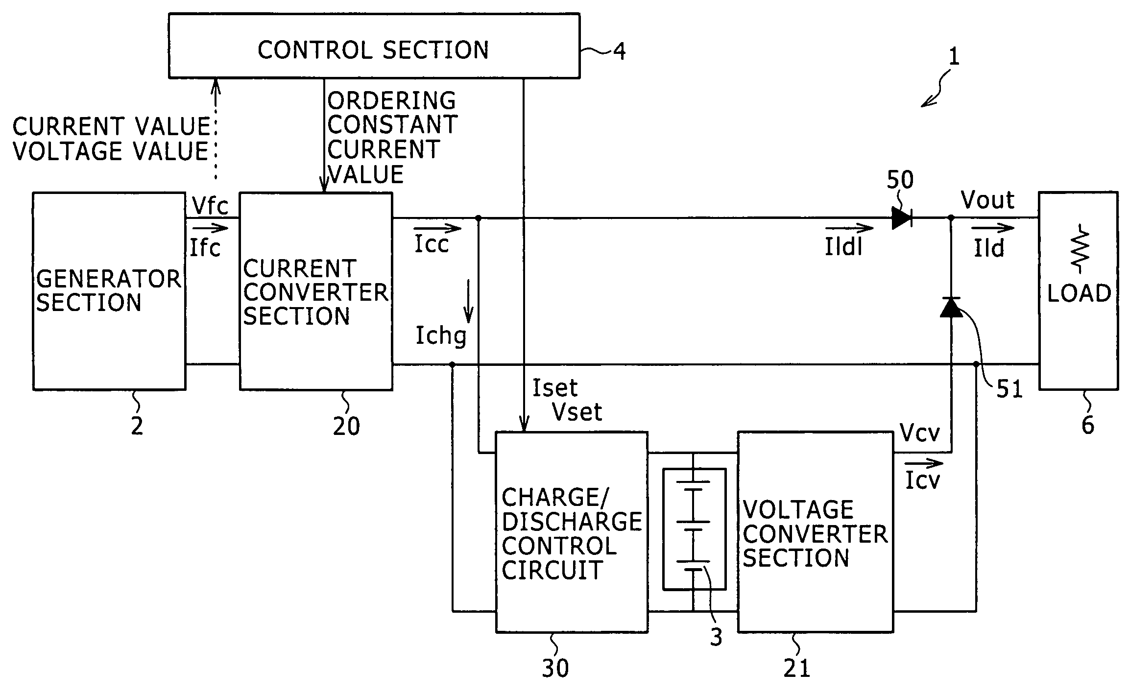
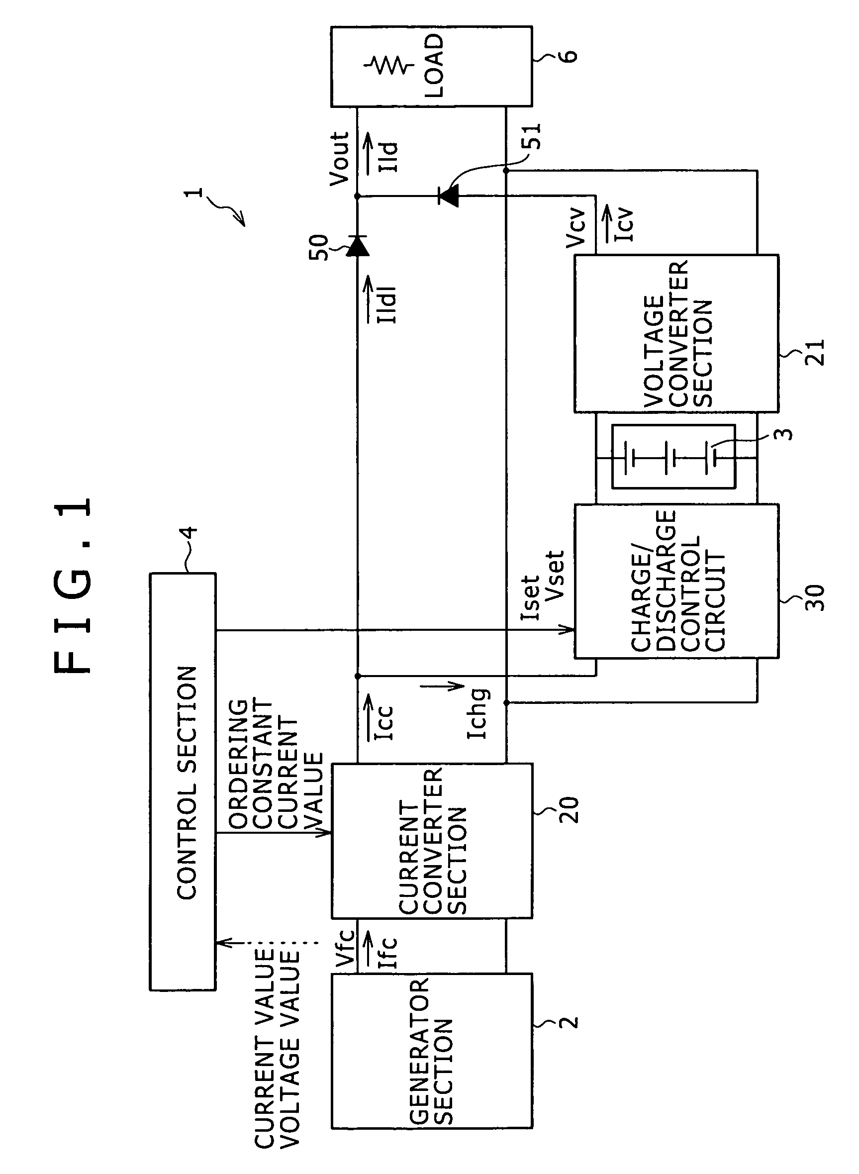
[0041]FIG. 1 is a view showing an example configuration of a power supply system according to an embodiment of the invention. A power supply system 1 according to the embodiment of the invention includes; a generator section 2 for performing power generation; a current converter section 20 for controlling an output from the generator section 2 so as to be a constant current; a power storage section 3 for performing charging and discharging; a charge / discharge control circuit 30 for controlling charging of the power storage section 3; a control section 4 for controlling the current converter section 20 and the charge / discharge control circuit 30 by orde...


PUM


Abstract

An output from a generator section is controlled by a current converter section to be a constant current. Charging and discharging of a power storage section is controlled by a charge / discharge control circuit. Thereby, even in a case where a current value required by a load is high, the case can be dealt with in the manner that, while an output current from the generator section is being maintained constant, the output from the generator section and an output from the power storage section can be caused to function in cooperation with each other. Further, charging and discharging of the power storage section can be performed by a simplified device.

Description

CROSS REFERENCES TO RELATED APPLICATIONS[0001]The present invention contains subject matter related to Japanese Patent Application JP 2004-176695 filed in the Japanese Patent Office on Jun. 15, 2004, the entire contents of which are incorporated herein by reference.BACKGROUND OF THE INVENTION[0002]1. Field of the Invention[0003]The invention relates to a power supply system, and more specifically, it relates to a power supply system wherein an output current from a generator section is maintained as constant to thereby secure stable operation of the generator section, and load current fluctuations are selectively compensated for by using an output from a power storage section, thereby enabling the outputs to function in cooperation with each other. In addition, the invention relates to an electronic device including the power supply system.[0004]2. Description of the Related Art[0005]Hitherto, there have been many proposals for power supply systems of the type wherein a power genera...

Claims


Application Information

Patent Timeline
Patent Type & Authority Patents(United States)
IPC IPC(8): H02J7/00
CPCH01M8/04589H01M8/04888H01M8/0494H01M8/04947H01M16/006H02J15/00H01M8/04007H01M2008/1095H01M2250/30Y02E60/50Y02B90/18Y02B90/10Y02E60/10H02J15/008H02J7/34H02M3/155
Inventor NOMOTO, KAZUTOSHI
Owner SONY CORP
Why Eureka
Try Eureka