Fiber optic device for measuring a parameter of interest

a fiber optic device and parameter technology, applied in the direction of instruments, heat measurement, cladding optical fibres, etc., can solve the problem of difficult to measure these two parameters independently of each other

Inactive Publication Date: 2009-05-26
HARRIS CORP
View PDF32 Cites 18 Cited by
  • Summary
  • Abstract
  • Description
  • Claims
  • Application Information

AI Technical Summary

Problems solved by technology

However, it is usually difficult to measure these two parameters independently of each other.

Method used


Image

  • Fiber optic device for measuring a parameter of interest
  • Fiber optic device for measuring a parameter of interest
  • Fiber optic device for measuring a parameter of interest

Examples


Embodiment Construction

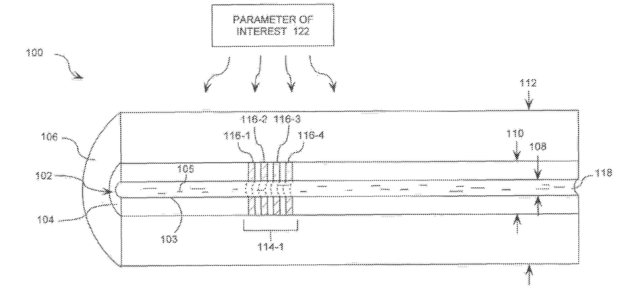
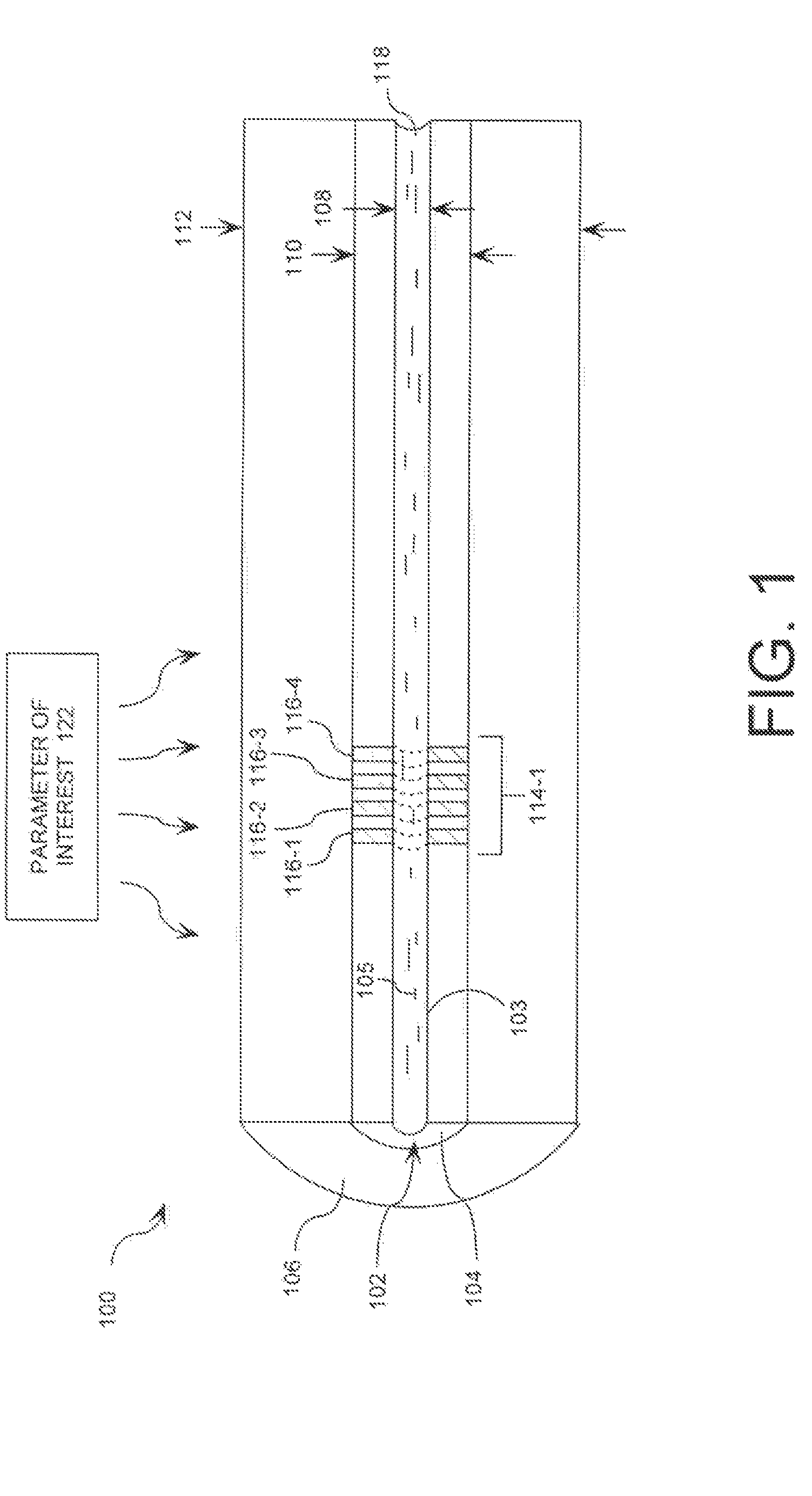
[0023]FIG. 1 is a cross-sectional view of an optical fiber 100 that can be utilized as a sensor for measuring a parameter of interest 122 such as temperature. The optical fiber 100 is an elongated structure comprised of a cylindrical core 102, a first optical cladding layer 104, an optical grating 114-1 disposed on the first optical cladding layer 104, and a second optical cladding layer 106. In the preferred embodiment of the invention, the core 102 is cylindrical. However, it should be understood that the cross-section of the core 102 can be of any shape including circular, elliptical, square, rectangular, and octagonal. The core 102 is comprised of a core material 105 to provide a waveguide for the propagation of a desired optical signal through the optical fiber 100. Such core materials include any media having an index of refraction and / or optical loss that is responsive to a parameter of interest such as temperature, photonic energy intensity, electric field intensity, and mag...


PUM


Abstract

An optical fiber (100) utilized as a sensor for measuring a parameter of interest 122 such as temperature, strain, photonic energy intensity, electric field intensity and magnetic field intensity is provided. A first optical cladding layer (104) is disposed on an optically transmissive core (102) that includes one or more optical gratings (114-1). The optical grating(s) (114-1) modifies a propagation path of selected wavelengths of light propagating through the core (102). The optical grating(s) (114-1) also varies the index of refraction of the first optical cladding layer (104). The selected wavelengths of light are determined in part by the index of refraction of the core material 105 as dependent upon a parameter of interest 122 applied to the core material 105 and as varied by the optical grating(s) (114-1). One or more detectors (410, 430, 450, 455) are used for determining the properties of the reflected and / or transmitted light. Knowing the properties of the reflected and / or transmitted light, a parameter of interest 122 can be determined.

Description

BACKGROUND OF THE INVENTION[0001]1. Statement of the Technical Field[0002]The invention concerns fiber optic devices, and more particularly, fiber optic devices utilized as a sensor for measuring a parameter of interest such as temperature.[0003]2. Description of the Related Art[0004]It is known in the art to utilize fiber optic devices for filtering an optical signal or measuring parameters of interest related to light propagating through an optical fiber. Optical fibers can be used for measuring a parameter of interest because changes to the environment in which the fiber resides can result in changes to material properties of the optical fiber that are sufficient to alter one or more characteristics of the propagating light such as the amplitude, phase, frequency, spectral content, or polarization of the light. By detecting the change in one or more of these characteristics, a parameter of interest can be measured. Such parameters of interest include the temperature and / or strain...

Claims


Application Information

Patent Timeline
Patent Type & Authority Patents(United States)
IPC IPC(8): G02B6/00
CPCG01K11/3206G01L1/246G01R15/241G01R33/032G02B6/021
Inventor DIMMICK, TIMOTHY E.SMITH, KEVIN H.MARKOS, DOUGLAS J.
Owner HARRIS CORP
Why Eureka
Try Eureka