Time division multiplexed signal receiver apparatus

a receiver apparatus and time division multiplex technology, applied in the field of time division multiplexed signal receiver apparatus, can solve the problems of frequency fluctuations and adversely affect the reception of signals, and achieve the effects of reducing the number of times of operation

Active Publication Date: 2009-05-26
PANASONIC CORP
View PDF16 Cites 7 Cited by
  • Summary
  • Abstract
  • Description
  • Claims
  • Application Information

AI Technical Summary

Benefits of technology

[0011]According to this construction, the quality of the received signal is evaluated by, for example, measuring a BER (Bit Error Rate) of the received signal, and the operation start time of the receiver circuit is determined based on a result of this evaluation. For instance, an early operation start time is set when the quality of the received signal is bad, and a late operation start time is set when the quality of the received signal is good. In this way, the receiver apparatus can start the operation of the receiver circuit with an effective timing in accordance with the quality of the received signal. This contributes to more power saving than conventional techniques.
[0012]Here, the evaluation unit may evaluate whether the quality of the received assigned signal is good, wherein the determination unit determines the operation start time to be closer to a time at which the reception of the next assigned signal begins, when the quality of the received assigned signal is better.
[0013]According to this construction, a later operation start time is set when the quality of the received signal is better. Hence the receiver apparatus can supply power to the receiver circuit with a more effective timing.
[0014]Here, the evaluation unit may set an evaluation value corresponding to the quality of the received assigned signal, and compare the evaluation value with a predetermined value to evaluate whether the quality of the received assigned signal is good, wherein the determination unit stores information showing a plurality of predetermined times beforehand, and determines, as the operation start time, a predetermined time that is closer to the time at which the reception of the next assigned signal begins when the quality of the received assigned signal is good, and a predetermined time that is farther from the time at which the reception of the next assigned signal begins when the quality of the received assigned signal is not good.
[0015]According to this construction, an early or late operation start time is set depending on the quality of the received signal. For example, if the signal quality varies within a predetermined range, predetermined times are provided beforehand as potential operation start times according to the signal quality, with it being possible to determine the operation start time efficiently.
[0016]Here, the evaluation unit may include: an error rate measuring unit operable to measure an error rate of the received assigned signal, wherein the evaluation unit performs the evaluation based on the measured error rate. Here, the evaluation unit may include: a C / N measuring unit operable to measure a carrier-to-noise ratio of the received assigned signal, wherein the evaluation unit performs the evaluation based on the measured carrier-to-noise ratio. Here, the evaluation unit may include: a reception input level estimation unit operable to estimate a reception input level of the received assigned signal, wherein the evaluation unit performs the evaluation based on the estimated reception input level. Here, the evaluation unit may include: a channel characteristic estimation unit operable to estimate a channel characteristic of the received assigned signal using pilot carriers contained in the received assigned signal, wherein the evaluation unit performs the evaluation based on the estimated channel characteristic. Here, the evaluation unit may include: an interference signal detection unit operable to detect whether power of each sub-carrier contained in the received assigned signal is larger than a predetermined value, wherein the evaluation unit performs the evaluation based on a result of the detection by the interference signal detection unit.

Problems solved by technology

By repeating power-on and power-off, a power supply voltage changes, which affects a PLL (Phase Locked Loop) circuit and causes frequency fluctuations.
This adversely affects signal reception, such as by preventing stable signal reception at a reception timing.

Method used


Image

  • Time division multiplexed signal receiver apparatus
  • Time division multiplexed signal receiver apparatus
  • Time division multiplexed signal receiver apparatus

Examples


first embodiment

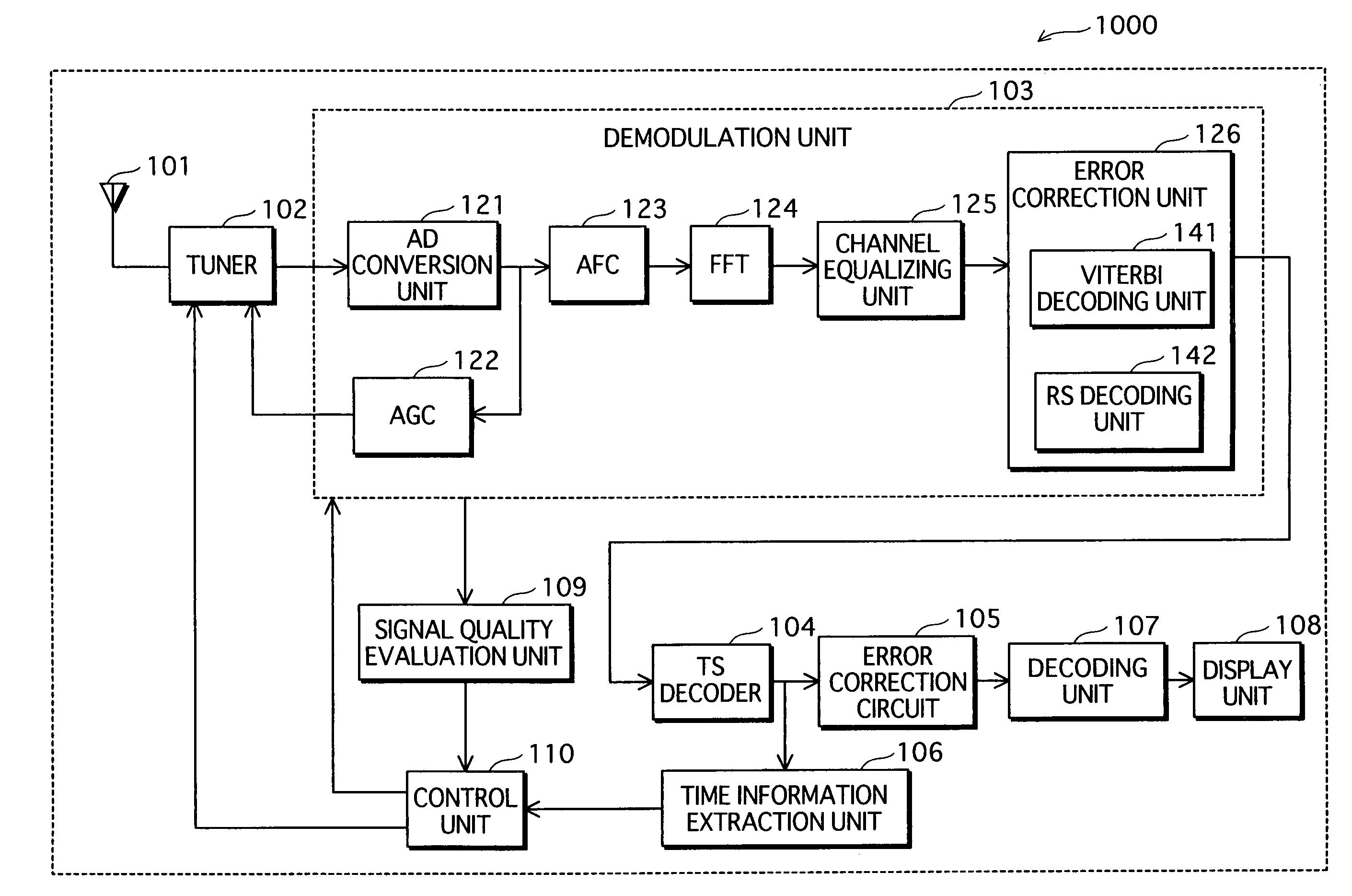
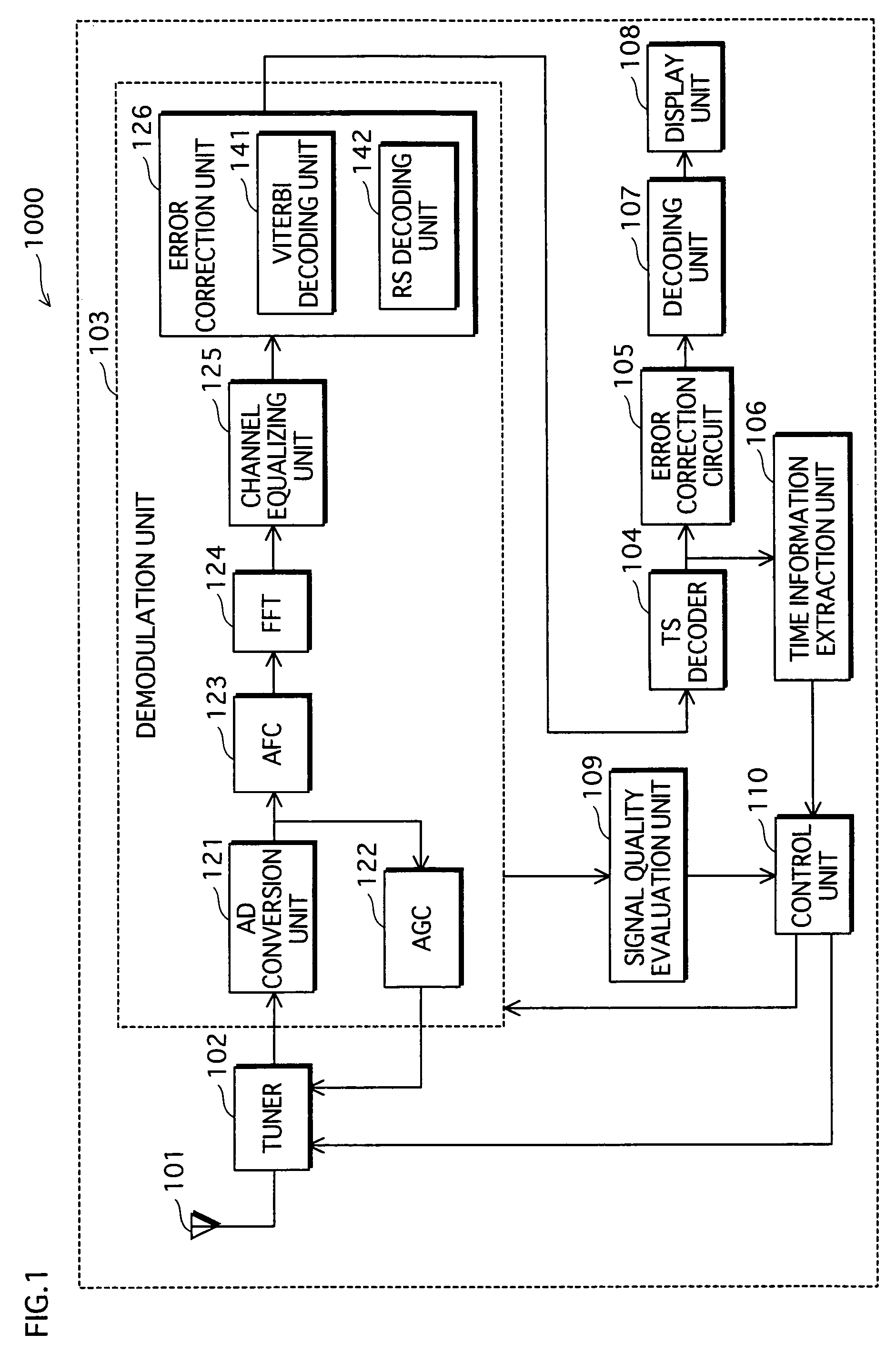
[0025]FIG. 1 is a functional block diagram showing a receiver apparatus according to a first embodiment.

[0026]A receiver apparatus 1000 shown in the drawing receives a time-division multiplexed signal according to, for example, DVB-H (Digital Video Broadcasting-Handheld). DVB-H is a transmission method that adapts data broadcasting of DVB-T (Digital Video Broadcasting-Terrestrial) which is a terrestrial digital television transmission method in Europe, for bringing broadcast services to mobile receivers.

[0027]As shown in the drawing, the receiver apparatus 1000 includes an antenna 101, a tuner 102, a demodulation unit 103, a TS (Transport Stream) decoder 104, an error correction circuit 105, a time information extraction unit 106, a decoding unit 107, a display unit 108, a signal quality evaluation unit 109, and a control unit 110. The demodulation unit 103 is composed of a plurality of circuits.

[0028]The antenna 101 receives a DVB-H broadcast signal which is transmitted by time-div...

second embodiment

[0073]The following describes a receiver apparatus according to a second embodiment.

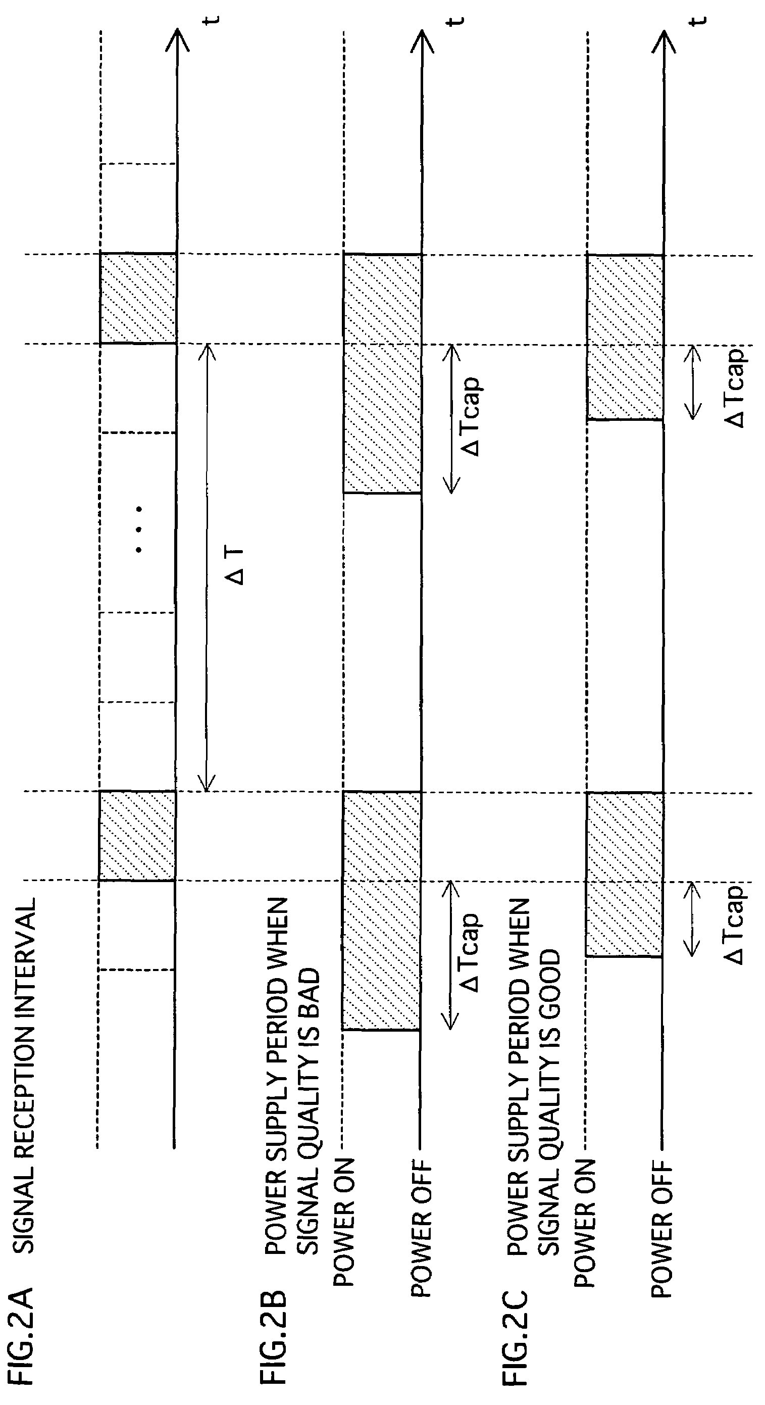
[0074]In the second embodiment, pull-in time ΔTcap is determined based on a previous pull-in time, when determining the operation start time. The following explanation mainly focuses on the difference from the first embodiment.

[0075]FIG. 6 is a functional block diagram showing the receiver apparatus of the second embodiment.

[0076]A receiver apparatus 1100 shown in the drawing differs from the receiver apparatus 1000 of the first embodiment, in that a pull-in time measuring unit 111 is provided in place of the signal quality evaluation unit 109. Construction elements such as the antenna 101 are the same as those of the first embodiment, and so their explanation has been omitted here.

[0077]The pull-in time measuring unit 111 has a timer function of counting a time, and may be constituted by a CPU, a ROM, a RAM, and the like. The pull-in time measuring unit 111 measures pull-in time ΔTcap, and stores on...

third embodiment

[0087]The following describes a receiver apparatus according to a third embodiment.

[0088]In the third embodiment, pull-in time ΔTcap is determined based on a remaining battery level of the receiver apparatus in addition to the quality of the received signal, when determining the operation start time. The following explanation mainly focuses on the difference from the first embodiment.

[0089]FIG. 8 is a functional block diagram showing the receiver apparatus of the third embodiment.

[0090]A receiver apparatus 1200 shown in the drawing includes a battery monitoring unit 112 in addition to the construction of the receiver apparatus 1000 of the first embodiment.

[0091]The battery monitoring unit 112 measures the remaining battery level of the receiver apparatus 1200, and outputs the measured remaining battery level to the control unit 110 in percentage as one example.

[0092]The control unit 110 controls the timing to supply power to the tuner 102 and the like based on the quality of the rec...


PUM


Abstract

To realize power saving of a receiver apparatus for receiving time-division multiplexed signals. In the receiver apparatus, power is supplied to a receiver circuit in accordance with an operation start time. A signal is received through the receiver circuit, and a quality of the received signal is evaluated by a signal quality evaluation unit 109. Control is exercised to set a late operation start time if the quality of the received signal is good, and an early operation start time if the quality of the received signal is bad. In this way, a period for supplying power to the receiver circuit can be adjusted according to the quality of the received signal. This makes it unnecessary to fix, as in conventional techniques, a long power supply period in consideration of the case where the signal quality is bad. As a result, more power saving can be achieved.

Description

TECHNICAL FIELD[0001]The present invention relates to a receiver apparatus for receiving time-division multiplexed signals, and especially relates to power saving techniques.BACKGROUND ART[0002]To receive a desired signal from a time-division multiplexed signal, a receiver apparatus that switches a power supply to a receiver circuit on and off according to signal reception timings has conventionally been used as shown in patent document 1 (see patent document 1).[0003]The receiver apparatus shown in patent document 1 starts the power supply to the receiver circuit a predetermined time before reception of a signal begins, in order to suppress adverse effects caused by repeating power-on and power-off. One example of such adverse effects is as follows. By repeating power-on and power-off, a power supply voltage changes, which affects a PLL (Phase Locked Loop) circuit and causes frequency fluctuations. This adversely affects signal reception, such as by preventing stable signal recepti...

Claims


Application Information

Patent Timeline
Patent Type & Authority Patents(United States)
IPC IPC(8): H04B1/18H04M1/00H04B1/16H04B1/40
CPCH04W52/0245Y02B60/50H02K5/225Y02D30/70
Inventor KANNO, IPPEI
Owner PANASONIC CORP
Why Eureka
Try Eureka