Vehicle-mounted alternator

a technology of vehicle-mounted alternators and alternators, which is applied in the direction of engine starters, electric generator control, dynamo-electric converter control, etc., can solve the problems of difficult implementation of such a scheme, and the inability to use an alternator driven by the engine always in the optimal state, so as to achieve the effect of reducing magnetic nois

Inactive Publication Date: 2009-06-02
DENSO CORP
View PDF7 Cites 9 Cited by
  • Summary
  • Abstract
  • Description
  • Claims
  • Application Information

AI Technical Summary

Benefits of technology

[0016]According to the present invention, it is possible to provide a vehicle-mounted alternator having a capability of effectively reducing magnetic noise thereof in accordance with a resonance frequency of a mounting structure thereof, and a rotation speed of a rotor thereof.

Problems solved by technology

However, since it is desirable to standardize the shape and size of a stator core from a production view point, it is difficult to implement such a scheme.
In addition, since the frequency at which magnetic noise can be reduced (or cannot be reduced) varies depending on a rotation speed of an engine, it is impossible to use an alternator driven by the engine always in an optimum state.

Method used


Image

  • Vehicle-mounted alternator
  • Vehicle-mounted alternator
  • Vehicle-mounted alternator

Examples


Embodiment Construction

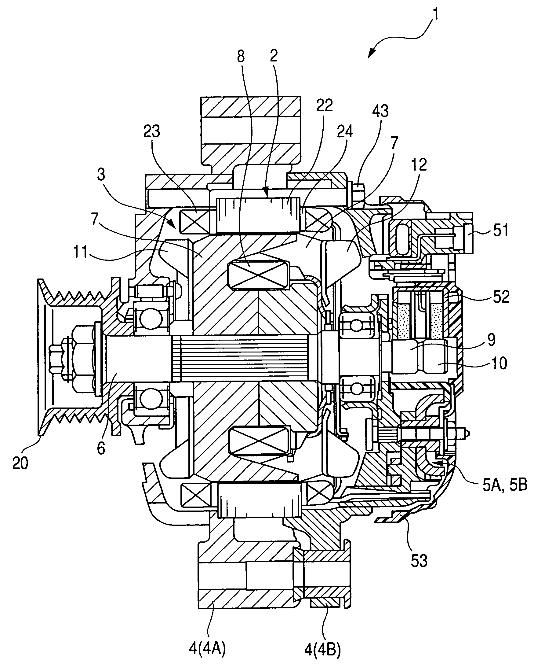
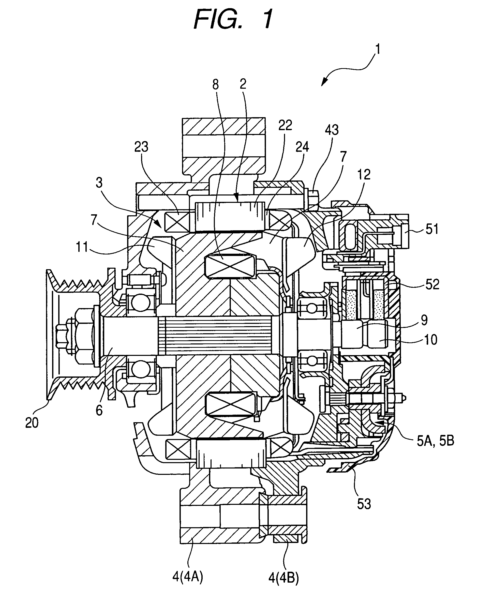
[0028]FIG. 1 is a diagram showing an overall structure of a vehicle-mounted alternator 1 according to an embodiment of the invention. The alternator includes a stator 2, a rotor 3, a frame 4, a first rectifier device 5A, a second rectifier device 5B, and a regulator 51.

[0029]The stator 2 is constituted by a stator core 22, a stator winding 23 wound around the stator core 22, and an insulator 24 providing electrical insulation between the stator core 22 and the stator winding 23. The stator core 22, which is formed by laminating thin steel plates, has a plurality of (72 in this embodiment) slots formed in an inner periphery thereof.

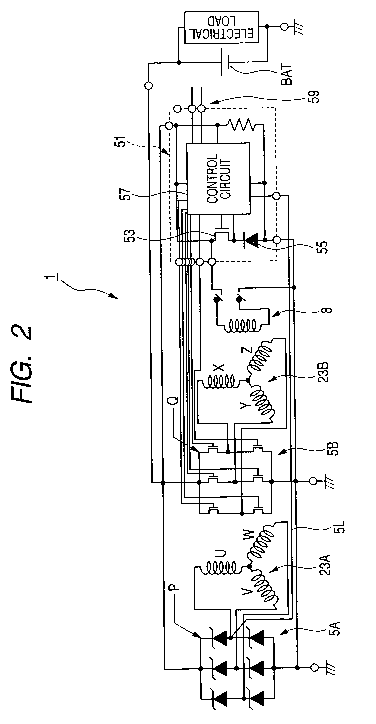
[0030]The stator winding 23 is constituted by a first three-phase winding 23A and a second three-phase winding 23B. The details of the first and second three-phase windings 23A and 23B will be explained later.

[0031]The rotor 3, which rotates together with a shaft 6, includes a Lundell-type pole core 7, a rotor winding 8 as a field coil, slip rings 9 and 10...


PUM


Abstract

The stator of the vehicle-mounted alternator includes a stator core formed with a plurality of slots located along a circumferential direction thereof, and first and second multi-phase windings wound in the slots, the first and second multi-phase windings being spaced from each other by a predetermined electrical angle. An output of the first multi-phase winding is rectified by a first rectifier device, and an output of the second multi-phase winding is rectified by a second rectifier device. The second rectifier device is constituted by a plurality of switching devices. The vehicle-mounted alternator includes a control device to perform on / off control on the switching devices such that a phase angle difference between an output of the first rectifier device and an output of the second rectifier device is varied depending on a rotation speed of the stator.

Description

CROSS-REFERENCE TO RELATED APPLICATION[0001]This application is related to Japanese Patent Application No. 2007-250453 filed on Sep. 27, 2007, the contents of which are hereby incorporated by reference.BACKGROUND OF THE INVENTION[0002]1. Field of the Invention[0003]The present invention relates to an alternator mounted on a vehicle such as a passenger car or a truck.[0004]2. Description of Related Art[0005]In recent years, there has been an increasing demand for vehicle alternators driven by an engine mounted on a vehicle, which generate less magnetic noise when generating power, in order to contribute to upgrading the vehicle. However, on the other hand, there has been an increasing demand for vehicle alternators having high power generation capacity because of an increase of electrical load due to an increased number of safety control devices and the like mounted on the vehicle. Accordingly, it has been required to provide small-sized, low-noise, and high-output vehicle alternator...

Claims


Application Information

Patent Timeline
Patent Type & Authority Patents(United States)
IPC IPC(8): F02N11/04
CPCH02P9/48H02K1/165H02K3/28H02K19/365H02K2213/03
Inventor OOIWA, TOORU
Owner DENSO CORP
Why Eureka
Try Eureka