Noise reduction apparatus

a noise reduction and apparatus technology, applied in the field of noise reduction devices, can solve problems such as difficulty in effective noise reduction, and achieve the effect of effective noise reduction

Inactive Publication Date: 2009-02-12
TAKENAKA KOMUTEN CO LTD
View PDF4 Cites 9 Cited by
  • Summary
  • Abstract
  • Description
  • Claims
  • Application Information

AI Technical Summary

Benefits of technology

[0013]In the noise reducing device of the present invention, since control sound is emitted in plural directions from speaker unit(s), effective noise reduction may be made even for noise propagated from plural directions.

Problems solved by technology

However, in the above described technology, since linear array sound sources such as speakers with speakers arranged in a straight line are used, then the control sound is emitted from each of the speakers simultaneously, sound emission only has a strong sound pressure level in a single direction.
Due to this, when there are moving noise sources, such as the noise from vehicles traveling on an expressway, since noise propagates to the noise reduction control points from various directions, it is difficult to carry out effective noise reduction.

Method used


Image

  • Noise reduction apparatus
  • Noise reduction apparatus
  • Noise reduction apparatus

Examples


first exemplary embodiment

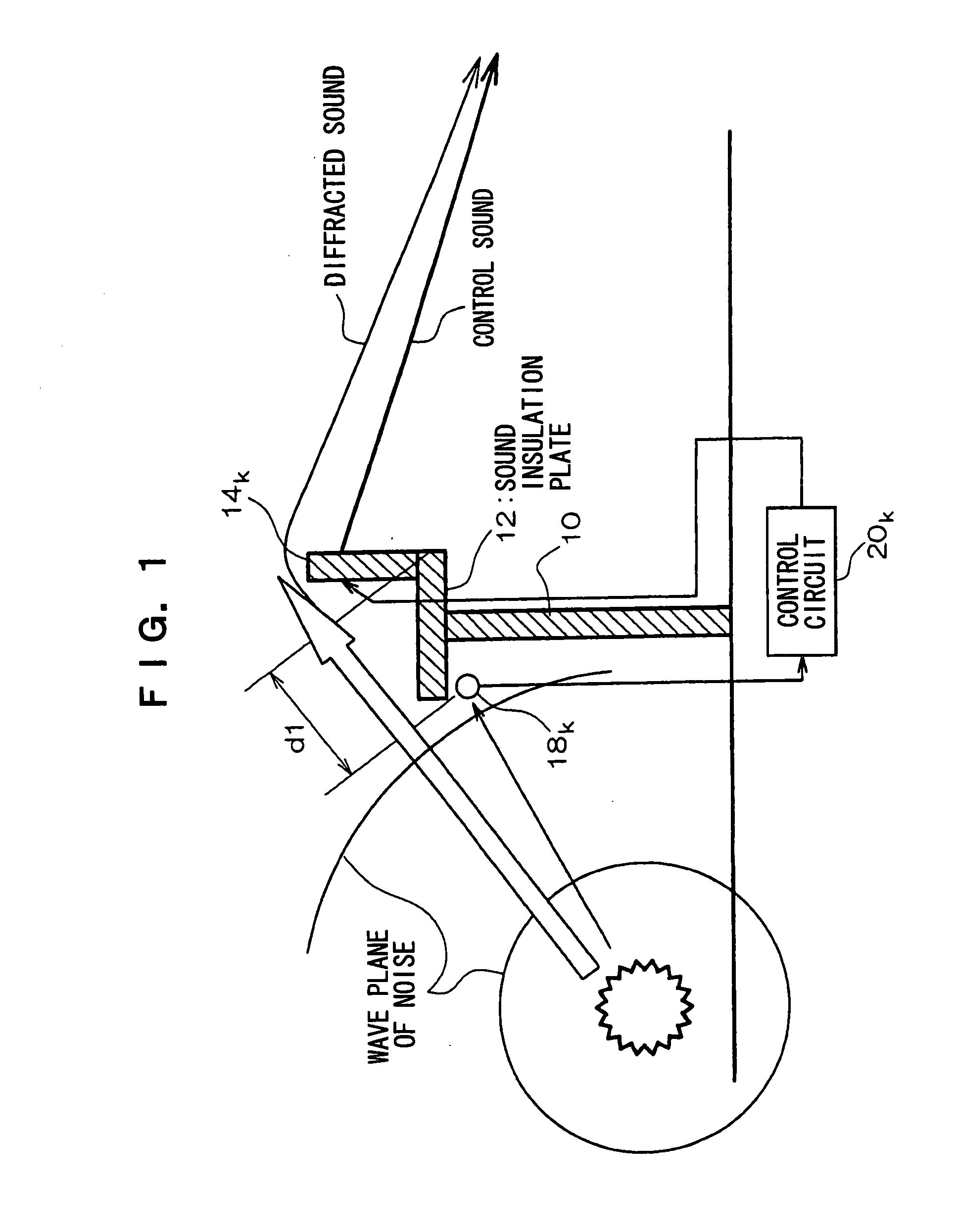
[0024]The present exemplary embodiment is where the present invention is applied to reducing diffracted noise cut from an expressway sound barrier and propagated to the outside of the sound barrier, by using a controlled sound source (secondary sound source) placed to the outside of the sound barrier.

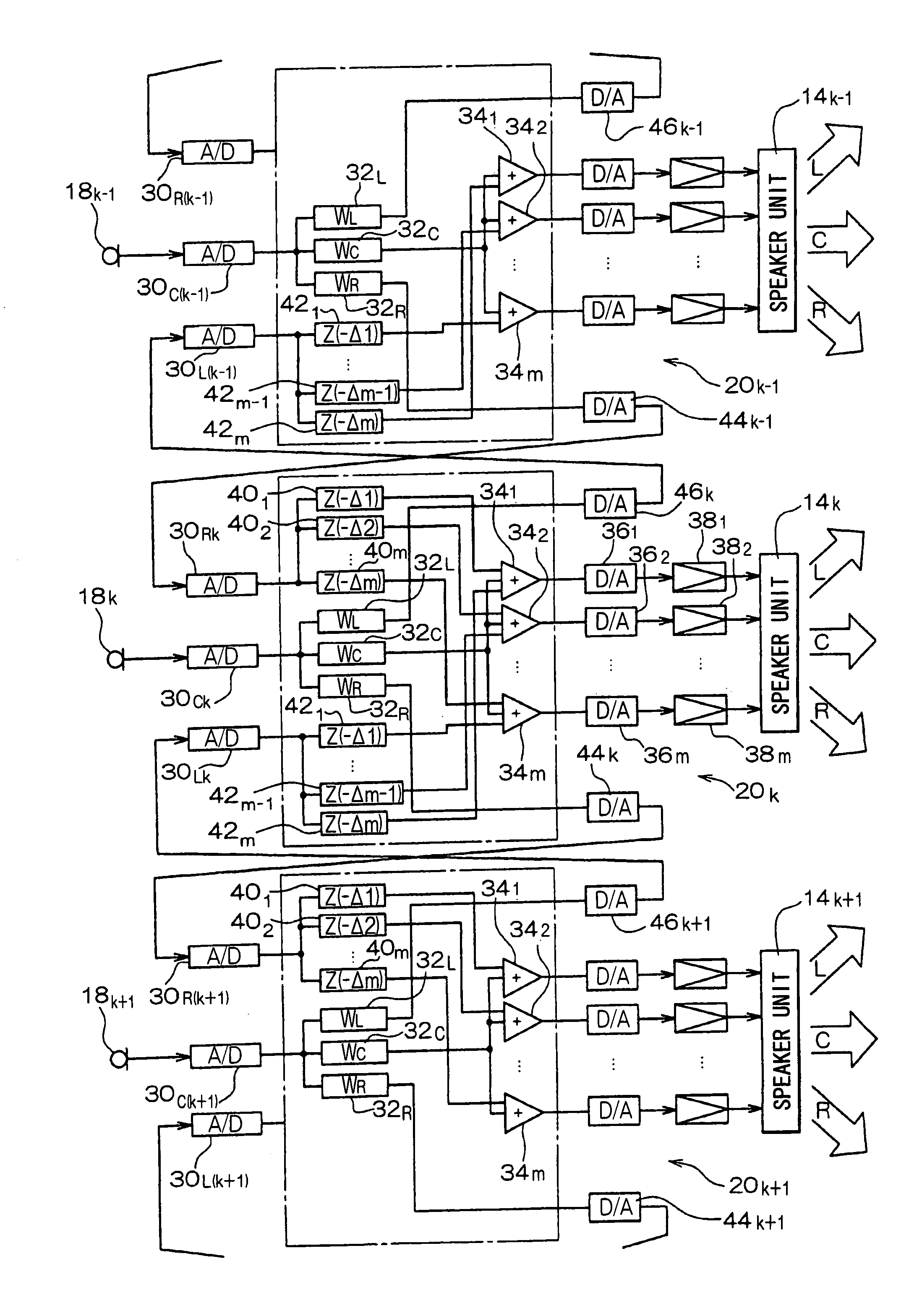
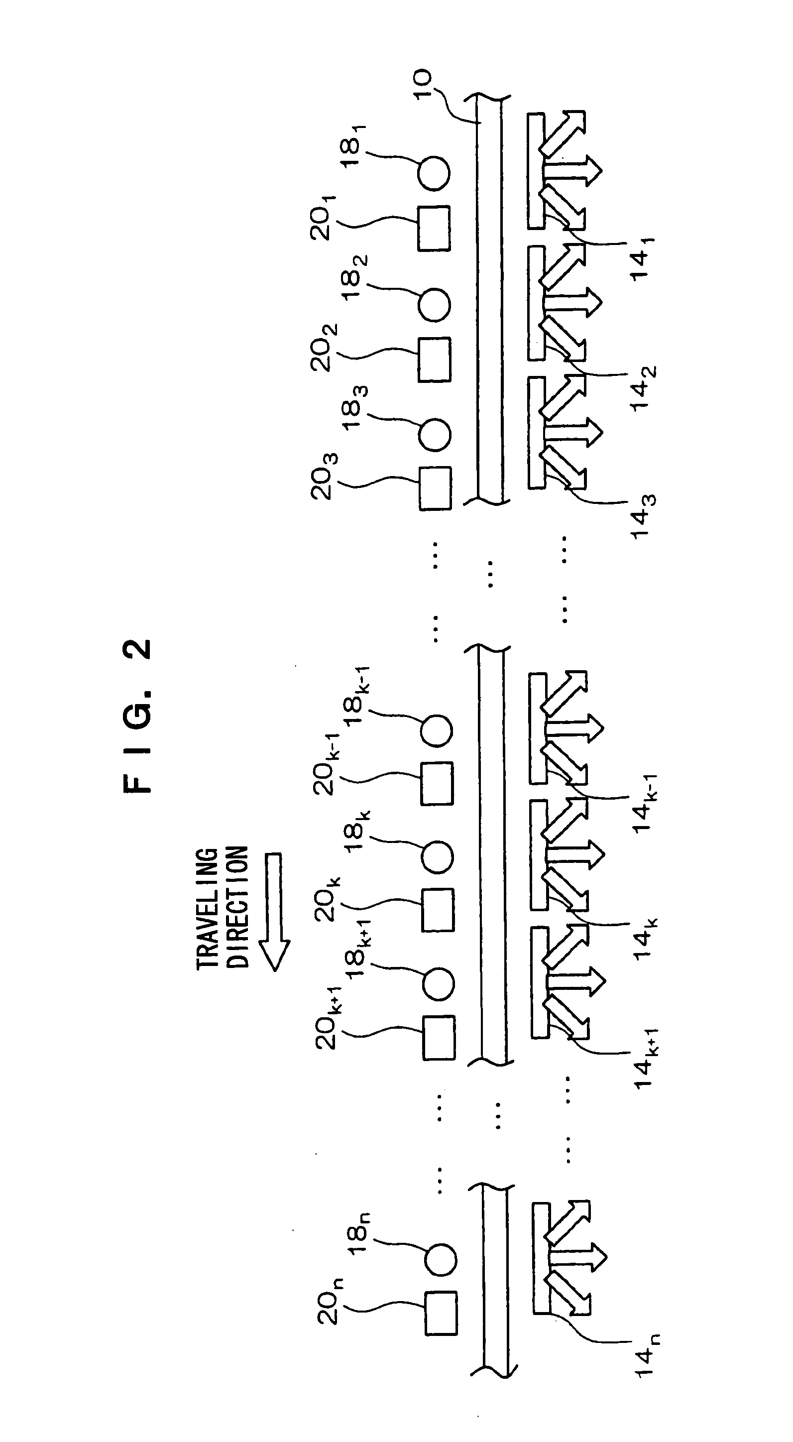
[0025]As shown in FIG. 1, there is a sound insulation plate 12 attached horizontally and continuously at the top edge of an expressway sound barrier 10 and along the top edge of the sound barrier 10. The sound insulation plate 12 contributes to preventing the generation of howling between the sensor / microphone and the controlled sound source (secondary sound source). The sound insulation plate 12 is not always necessary, and a howling prevention circuit may be introduced for controlling the generation of howling. Plural speaker units 141, 142, 143, . . . 14k−1, 14k, 14k+1, . . . , 14n (k and n are positive integers with k12 and at the outside of the sound barrier on the top face of the ...

second exemplary embodiment

[0058]Explanation will next be given of a second exemplary embodiment of the present invention with reference to FIG. 7. In the present exemplary embodiment, there is an external air temperature sensor 50 disposed therein for detecting the external air temperature, a coefficient correction unit 52 is provided to each of the control circuits, and correction is carried out in the coefficient correction unit 52 using respective filter coefficients according to the external air temperature. The correction coefficients for correcting the filter coefficients according to the external air temperature are stored in advance in the respective coefficient correction units 52, and the coefficient correction units 52 read out the correction coefficients according to the external air temperature that has been detected and carry out correction of the filter coefficients of the inverse filters.

[0059]By so doing, the diffracted sound of the noise may be effectively reduced even if the speed of sound...

third exemplary embodiment

[0061]The third exemplary embodiment uses adaptive filters for the inverse filters 32R, 32C and 32L, as shown in FIG. 8, a microphone 54 is arranged for detecting at the control point P the signal error between the control sound and the diffracted sound of the noise, and correction is carried out of the filter coefficients of the adaptive filters so that the signal error of a coefficient correction device is as small as possible.

[0062]In doing so, the diffracted sound of the noise may be effectively reduced even if there is a change in the environment, since control may be carried out so that the signal error between the control sound and the diffracted sound of the noise is as small as possible.

[0063]In the above exemplary embodiments, explanation was given of a case in which the diffracted sound of the noise is reduced, however, the present invention is applicable to reducing the direct noise that is propagated to control points without diffraction. In such a case, control sound i...


PUM


Abstract

Effective reduction is made of direct sound or diffracted sound of a noise propagating from plural directions. Three microphones (18k−1, 18k, 18k+1) are disposed and: noise is detected by each of the microphones; delay signals are generated by delaying plural times a signal that has been output from 2 of the microphones (18k−1, 18k+1); the output signal from the remaining microphone (18k) is added to 2 of the delayed signals and input to respective speakers of a speaker unit; a control sound is output from the speaker unit in 3 directions (L, C, R); and reduction is made of direct sound or diffracted sound of a noise propagating from each of the directions.

Description

TECHNICAL FIELD[0001]The present invention relates to a noise reducing device, and in particular to a noise reducing device for reducing, at the outside of a sound barrier, noise that is generated when moving bodies move, for example, noise that has been generated by vehicles traveling on an expressway.BACKGROUND ART[0002]Conventionally known in which speakers are disposed at the top edge of the sound insulation barrier and along the top edge of the sound insulation barrier, and noise that has been diffracted from the sound insulation barrier is suppressed by sound waves of opposite phase being emitted from the speakers.[0003]Also, a noise reducing device is known in which, when suppressing noise using a control sound, linear sound source arrays of speaker units including plural arrayed speakers are disposed along the top edge of a sound barrier, and by using filter coefficients that have been computed by explicit methods and an acoustic signal of the noise that has been detected by...

Claims


Application Information

Patent Timeline
Patent Type & Authority Applications(United States)
IPC IPC(8): G10K11/16G10K11/178
CPCG10K11/1788G10K2210/124G10K2210/12G10K11/17821G10K11/17854G10K11/17857G10K11/17881
Inventor NAKAJIMA, TATSUMI
Owner TAKENAKA KOMUTEN CO LTD
Why Eureka
Try Eureka