Floating apparatus for deploying in marine current for gaining energy

a floating apparatus and current technology, applied in the direction of buoys, tidal streams/damless hydropower, artificial islands, etc., can solve the problems of reducing the potential power capture, reducing the current velocity, and reducing the type of bottom mounted devices

Active Publication Date: 2009-06-02
OCEAN FLOW ENERGY
View PDF21 Cites 58 Cited by
  • Summary
  • Abstract
  • Description
  • Claims
  • Application Information

AI Technical Summary

Problems solved by technology

The disadvantage of the seabed or bottom mounted device is that the current velocity tends to reduce with depth below the water surface thus reducing the potential power capture.
This type of bottom mounted device is also difficult to install as the support structure has to be fixed in place by a vessel or jack-up rig that can maintain its position in a sea area of strong tidal flow making marine operations difficult and dangerous.
Also the requirement to use a jack-up vessel for installation means that deployment in deep water is complex, expensive and has high safety risks and this limits the number of tidal locations where this type of solution can be applied.
Seabed fixed solutions require special means for efficiently extracting energy from bi-directional currents such as tidal currents and these can involve expensive and complex solutions such as variable pitch turbine blades or turbine and nacelle pods that rotate through 180 degrees with each change in tide cycle to efficiently extract energy from flow from the opposite direction.
The disadvantage of a surface float is that it is subject to wave induced whole body motions which are transmitted to the turbines and generators and reduce the efficiency of the turbine and increase the design loads on the fixed and rotating machinery, particularly the turbine blades.
A surface float also attracts large forces from the wave which increases the size and cost of the mooring system.
In addition, the wave particle velocity is at a maximum near the sea surface and may act to counter the steady tidal or ocean current velocity thus reducing the efficiency of a turbine mounted near the surface as in WO 88 / 04362.
Allowing the device to pivot freely about its mooring system raises the complexity of how to avoid entanglement of the mooring lines with the power export umbilical.
If the device were allowed to build up rotation in one particular direction it would eventually lead to twist and possible damage to the umbilical.

Method used


Image

  • Floating apparatus for deploying in marine current for gaining energy
  • Floating apparatus for deploying in marine current for gaining energy
  • Floating apparatus for deploying in marine current for gaining energy

Examples


Embodiment Construction

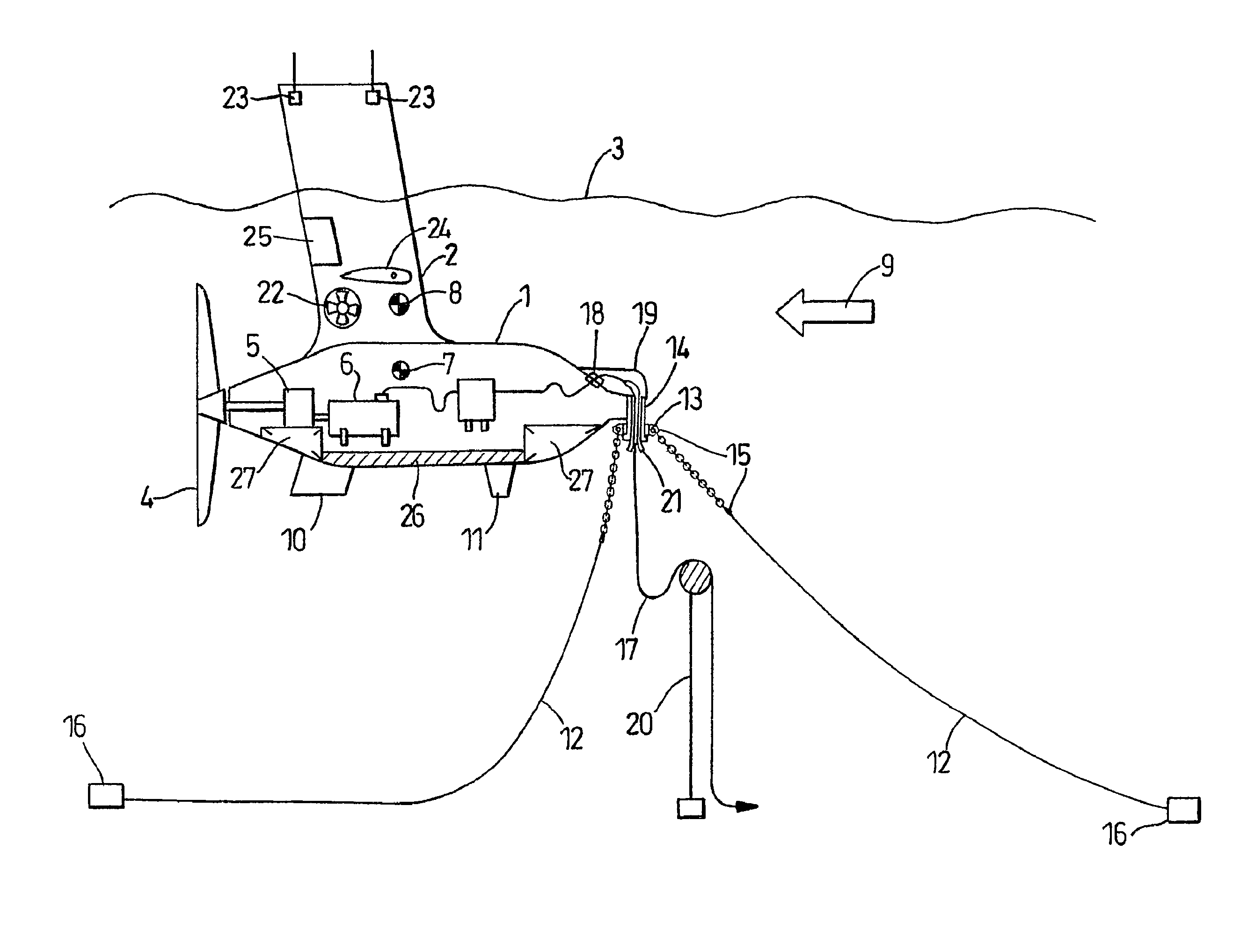
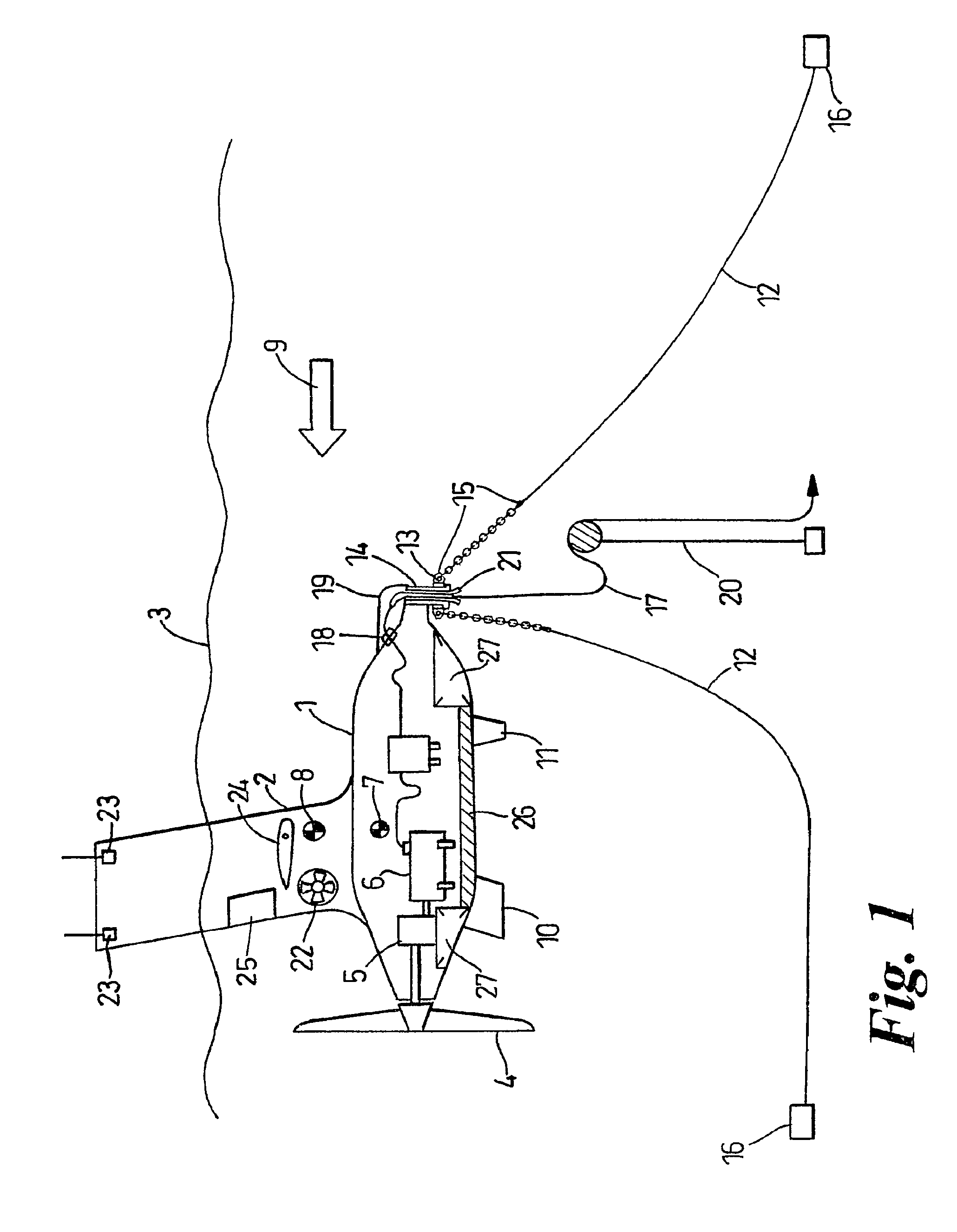
[0033]The embodiment of the invention shown in FIGS. 1, 3 and 4 is a mono-hull variant with a single vertical strut. The device consists of a submerged nacelle body (1) with a substantially vertical strut (2) that pierces the water surface (3). The strut piercing the water surface is of small waterplane area such that it does not attract large changes in buoyancy with change in wave elevation. The submerged body (1) supports a hydro turbine (4) which drives through a step-up gearbox (5) which is coupled to a generator (6) for extracting power from marine currents. The geometry of the submerged nacelle body plus surface piercing strut is arranged such that the still water centre of gravity [CoG] (7) aligns longitudinally with the centre of buoyancy [CoB] (8) of the device taking account of the additional trimming moment induced by the mooring system and that the CoB is vertically above the CoG thus ensuring the positive stability of the device.

[0034]The surface piercing strut (2) is ...


PUM


Abstract

A floating, semi-submerged, tethered device that supports a horizontal axis turbine and power generation equipment for extracting kinetic energy from a tidal stream or ocean current. A submerged body (1) is supported by surface piercing struts (2) of small water plane area (FIG. 6). The device is tethered to the seabed by a spread of mooring lines (12) that are deployed both into and away from the direction of the tidal current. A horizontal axis turbine (4) harnesses energy from the water flow and drives a generator housed within the body. A horizontal strut hydrofoil (24) corrects the trim of the device when subject to varying loads from the mooring system and can also be used to dampen pitch motion. Rudder flaps in the struts (25) can be used to counteract roll motion. Power is exported from the device to the seabed by an umbilical (17). A thrusters (22) can be used to constrain the rotation of the device about its mooring system to prevent excessive twist building up between the mooring lines and the power export umbilical.

Description

[0001]This application is the National Phase of International Application PCT / GB2005 / 004432 filed Nov. 17, 2005, which designated the U.S. That International Application was published in English under PCT Article 21(2) on May 26, 2006 as International Publication Number WO 2006 / 054084A1. PCT / GB2005 / 004432 claims priority to U.K. Application No. 0425303.5, filed Nov. 17, 2004. Thus, the subject nonprovisional application claims priority to U.K. Application No. 0425303.5, filed Nov. 17, 2004. The disclosures of both applications are incorporated herein by reference.FIELD OF THE INVENTION[0002]The present invention relates to an apparatus for extracting energy from marine, ocean or tidal currents, and in particular to a vessel that in use is semi-submerged.BACKGROUND OF THE INVENTION[0003]The extraction and use of finite energy resources and more recently the phenomenon of global warming have lead to interest in extracting energy from renewable energy resources such as wind, wave and t...

Claims


Application Information

Patent Timeline
Patent Type & Authority Patents(United States)
IPC IPC(8): F03B13/00
CPCF03B13/26F03B17/061E02B2017/0091Y02E10/38Y02E10/28Y02E10/30F03B13/10Y02E10/20
Inventor MACKIE, GRAEME CHARLES
Owner OCEAN FLOW ENERGY
Why Eureka
Try Eureka