Automatic bright band detection and compensation

a bright band detection and compensation technology, applied in the field of weather radar, to avoid incorrect assessment of weather threats

Active Publication Date: 2009-06-02
ROCKWELL COLLINS INC
View PDF16 Cites 68 Cited by
  • Summary
  • Abstract
  • Description
  • Claims
  • Application Information

AI Technical Summary

Benefits of technology

[0019]It is an advantage of the present invention to provide an inference based system and a detection based system for bright band.
[0020]It is an advantage of the present invention to provide bright band detection and compensation for an existing weather radar system with little modification.
[0021]It is a feature of the present invention to provide bright band detection and compensation to avoid incorrect assessment of a weather threat by an aircrew.

Problems solved by technology

The processor reduces or eliminates reduction of the encoded return level when the aircraft is at medium to high altitudes with a freezing attitude thousands of feet below the aircraft due to substantial uncertainties about bright band location.

Method used


Image

  • Automatic bright band detection and compensation
  • Automatic bright band detection and compensation
  • Automatic bright band detection and compensation

Examples


Embodiment Construction

[0034]The present invention is for a weather radar system capable of bright band detection and compensation.

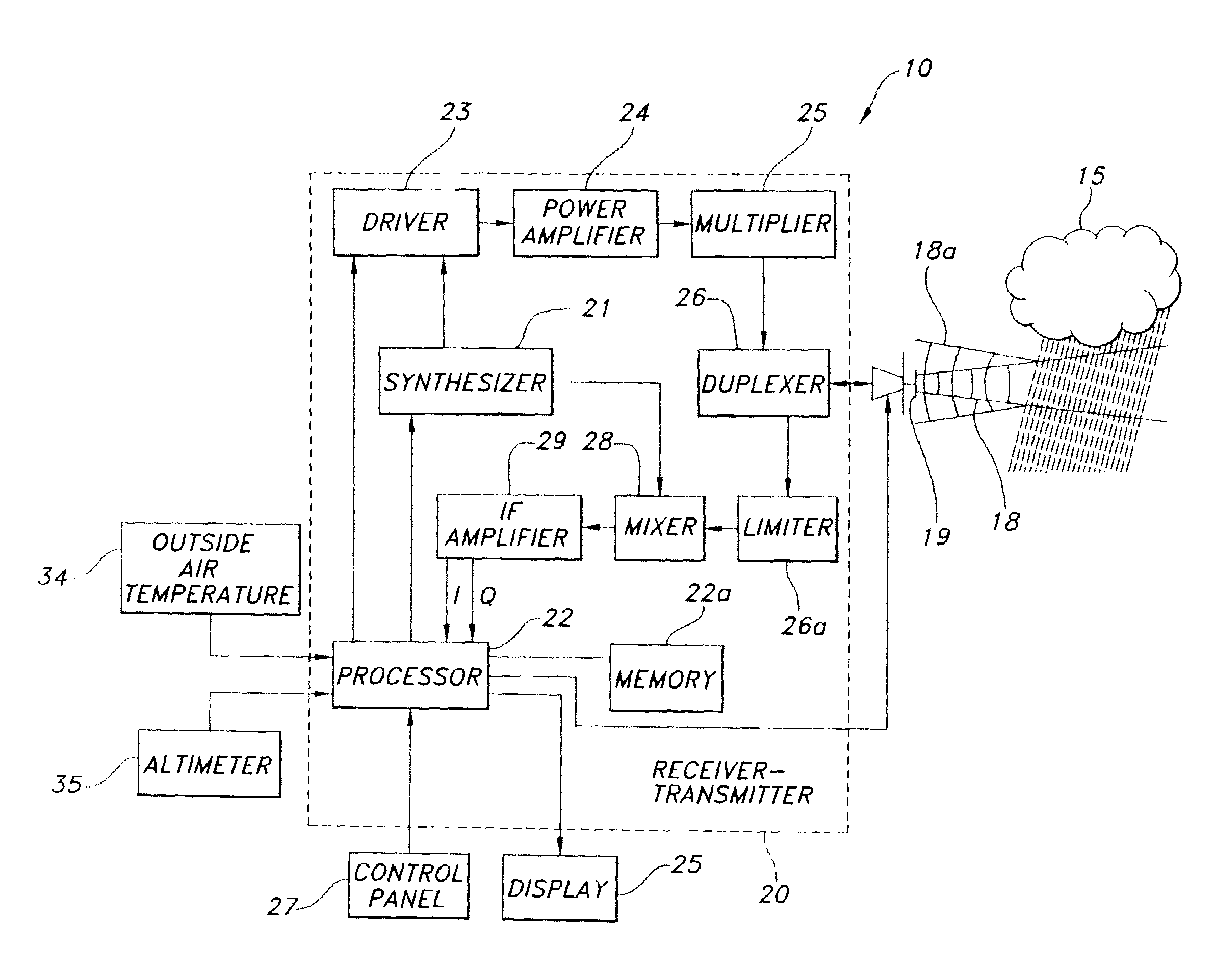
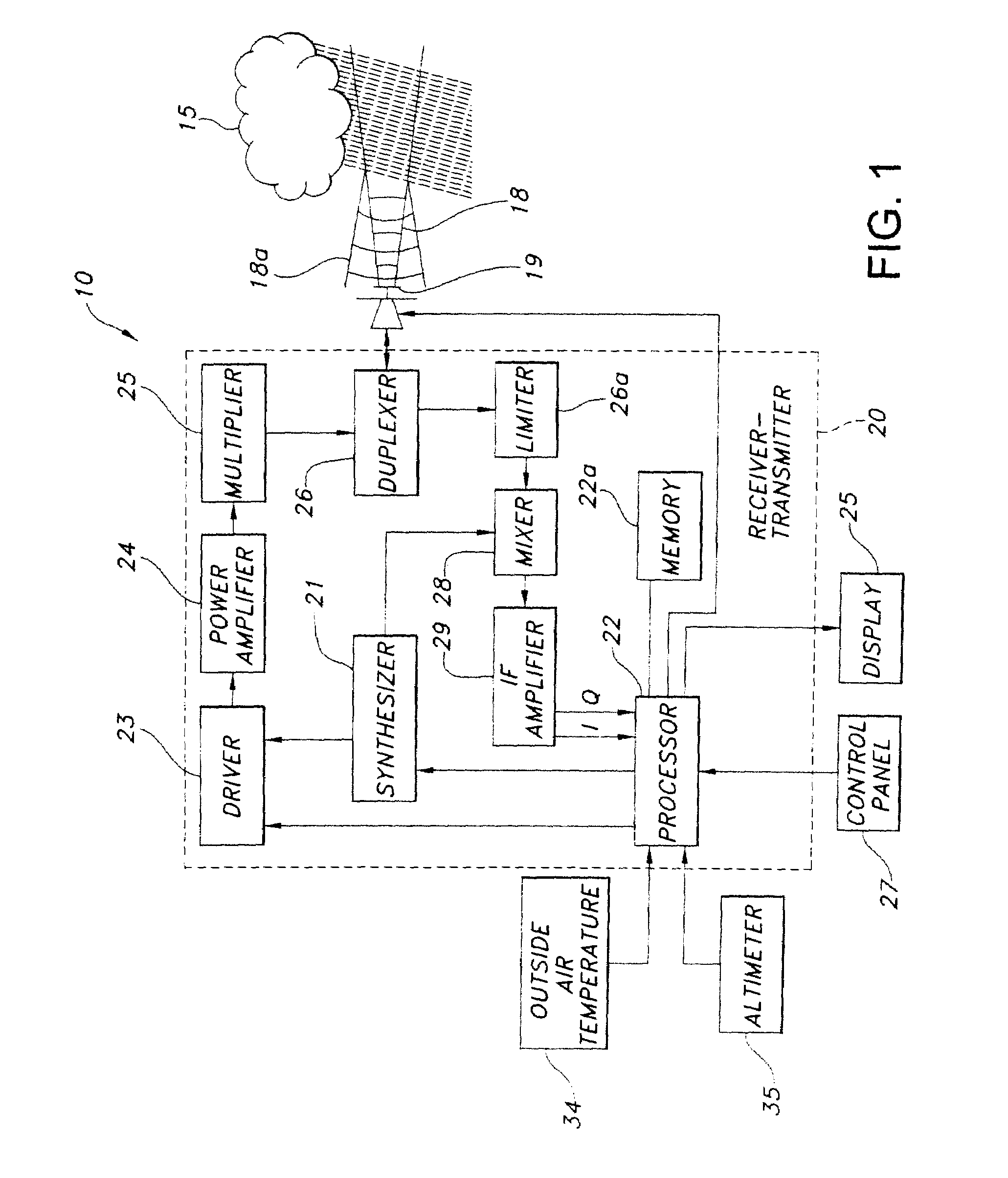
[0035]Weather radars are known in the art for detecting severe weather and for providing a flight crew in an aircraft a two-dimensional map display showing range, bearing, and intensity of detected weather patterns. Flight hazards due to weather conditions are primarily the result of precipitation and turbulence. A block diagram of a representative weather radar 10 that may incorporate the present invention for bright band detection and compensation is shown in FIG. 1. The weather radar 10 may be a WXR-2100 MULTISCAN™ Weather Radar System manufactured by Rockwell Collins Inc. and is used herein as an exemplary weather radar system in which to incorporate the present invention.

[0036]In FIG. 1 pulses 18 are transmitted from the weather radar system 10 using antenna 19 and reflected from a target 15 as return pulses 18a that are received by the antenna 19. Within a receiver-trans...


PUM


Abstract

A weather radar system has bright band detection and compensation. The weather radar system determines that high reflectivity in weather is a bright band and reduces an encoded return level from the bright band to compensate for it on a display. The weather radar system detects the presence of the bright band using an inference system that uses outside air temperature, aircraft altitude, and an assumed lapse rate to estimate the bright band location relative to the aircraft and uses antenna elevation to estimate bright band range to reduce the encoded radar return level on the display. The weather radar system may also detect the presence of the bright band using a detection system that uses radar estimates from normal reflectivity scan operation of the system. The weather radar system may also use an active detection process separate from a normal radar sampling process to detect the bright band.

Description

CROSS-REFERENCE TO RELATED PATENT APPLICATIONS[0001]This application is a continuation of and claims priority to U.S. application Ser. No. 11 / 039,753, filed Jan. 20, 2005, incorporated herein by reference in its entirety.BACKGROUND OF THE INVENTION[0002]This invention relates to weather radar and specifically for an airborne weather radar system capable of bright band detection and compensation.[0003]Weather radars are known in the art for detecting and displaying severe weather to a crew in an aircraft on a two-dimensional map display showing range, bearing, and intensity of detected weather patterns such as convective or stratiform weather patterns. Flight hazards due to weather conditions are primarily the result of precipitation and turbulence. Airborne weather radar has been optimized to detect rain since rain drops act as an excellent reflector for the radar's microwave energy. Dry snow and ice crystals are very poor reflectors of radar energy. Wet hail provides the strongest ...

Claims


Application Information

Patent Timeline
Patent Type & Authority Patents(United States)
IPC IPC(8): G01S13/95G01S7/04G01S7/285G01S13/00
CPCG01S7/285G01S13/953Y02A90/10
Inventor WOODELL, DANIEL L.ROBERTSON, ROY E.
Owner ROCKWELL COLLINS INC
Why Eureka
Try Eureka