Eye tracking head mounted display

a display and head technology, applied in the field of head mounted display systems, can solve the problems of unfavorable or difficult implementation of solutions, unfavorable use of huds, and unfavorable use of huds, and achieve the effects of easy maintenance, easy maintenance, and improved performan

Inactive Publication Date: 2009-06-02
TEDDER DONALD RAY
View PDF11 Cites 308 Cited by
  • Summary
  • Abstract
  • Description
  • Claims
  • Application Information

AI Technical Summary

Benefits of technology

[0019]In another embodiment, there is provided a head mounted display, with motors attached to a mount, and with beam-splitters attached to motors by rigid elements. The rigid elements remain essentially outside of the user's view, while allowing a beam-splitter to move in a spherical plane centered on one of the user's eyes. A beam-splitter is positioned in the user's line-of-sight, and an image projector with display producer projects images onto the beam-splitter. In this way, the user may simultaneously view projected images and objects behind the beam-splitters. Optionally, a second combination of motors, mounts, projector and beam-splitter may be disposed at the user's head, and the motion of the second beam-splitter centered on the other of the user's eyes. With two such combinations, the user simultaneously views three-dimensional projected images and real-world objects. An eye-tracker monitors the user's gaze with a camera attached to the rigid element and placed between the beam-splitter and the display. The camera has direct vision of the eye. The processor receives measurements from the eye-tracker. When the user moves his eyes, the processor uses these measurements in instructing the motors to move the beam-splitter back into the user's line-of-sight and the camera again looking directly into the user's eye. Two such eye-trackers may be used when two beam-splitters are used (again, one before each eye.) The rigid elements absorb undesirable resonance and vibrations that may occur while moving the beam-splitter. The motion of the beam-splitter is fast, and optionally not salient to the user. Additional optics and digital image control can be used to adjust the intensity, focus, and pixel distribution of the image to better match characteristics of the user's eye and the user's eye resolving power. Beam-splitters of varying transmission indices can be used to match the intensity of the image to the intensity of ambient light. Additional adjustments can be made to the image to compensate for any angular displacement from the user's eye.
[0020]In yet another embodiment, there is provided a head mounted display with beam-splitters attached to motors by a rigid element, wherein the motors move along the mount on tracks. The tracks can guide the beam-splitters in any combination of roll, pitch, and yaw about the center of each eye. The rigid element remains essentially outside of the user's view, while allowing the beam-splitters to move in a sphere where the center of all device rotations is about the center or rotation of the observer's eye. Additional motors attached between the beam-splitter and the mount can adjust the angle of the beam-splitter to maintain direct projection toward the user's eye. Again, a second combination of motors, mounts, projector and beam-splitter may be disposed at the user's head, and the motion of its beam-splitter centered on the other of the user's eyes.
[0021]In yet another embodiment, there is provided a head mounted display which uses both an eye-tracker and a head-tracker. The eye-tracker is in communication with a processor that commands the motors. The eye-tracker and head-tracker are both in communication with an image processor, which may be a second processor, or the same processor that commands the motors. The image processor uses the information from the eye-tracker and the head-tracker to select images for projection by the display. Again, a second combination of motors, mounts, projector and beam-splitter is disposed at the user's head, and the motion of its beam-splitter is centered on the other of the user's eyes. In this way, the display can present three-dimensional images which correspond to the real-world objects in the user's line-of-sight. The display can also present images which change as the user's view changes, creating a virtual environment for the user in which virtual objects can seem to exist in a fixed point in space. In this way, the user can look at or away from these objects by moving his eyes and / or head toward or away from them, respectively. The display can present images as if they are attached to the beam-splitter (and thus in a constant region of the user's eye's field of view), as if they are attached to a vehicle or other space occupied by the user, or as if they are attached to objects in the outside world (which may be moving independently of such a vehicle).
[0023]In yet another embodiment, measurements from the eye-tracker allow the user to control objects in the virtual environment with his gaze.

Problems solved by technology

HMDs are used in many more environments than so-called “heads-up displays” or HUDs, as HMDs may be worn by a user in many environments, including those in which the use of a HUD might be difficult or impossible.
For all their uses, however, HMDs have historically had a number of problems for which solutions have seemed either impossibly costly, or impossibly difficult to execute.
For example:To produce even a small display area, HMDs have typically required equipment that is bulky, heavy, unwieldy, uncomfortable, and expensive.Typical HMDs fail to cover all of the directions in which the eye can look, leading to a discontinuous image, an unenhanceable “blind spot,” or a lack of image altogether at the periphery.
Alternately, the use of a high display resolution requires a narrow and constricting field of view.While the distribution of rods, cones, and other structures within the eye is not even or symmetrical, HMDs typically produce the same pixel density and image type for every part of the eye, leading to a discontinuous, uncomfortable, and suboptimal viewing experience, which wastes information density where the eye is ill equipped to handle it.HMDs often produce images from a single source in space, leading to variations in the image perceived when the eye is at different angles from the source.
Systems to compensate for this angular distortion can involve digital alteration of the image, which can squander processing power and require specialized hardware.Delivering an image from a location on the HMD to the eye often requires a large number of optical components like mirrors, beam-splitters, and lenses.
For an example of a HMD which uses multiple mirrors in this manner, see U.S. Patent Application Publication No. 2002 / 0167462 to Lewis et al.HMDs which project directly onto the retina pose unique safety risks and alignment problems.
Such system designers often encounter an exponential increase in system complexity, as they must use twice the equipment and processing power to produce two images per eye, and then keep these images spatially and temporally synchronized at all times. Further, when the user turns his gaze outside of the inset area, the fovea of his eye is presented with low-density information, while his periphery receives high-density information, which is the opposite of ideal.

Method used


Image

  • Eye tracking head mounted display
  • Eye tracking head mounted display
  • Eye tracking head mounted display

Examples


Embodiment Construction

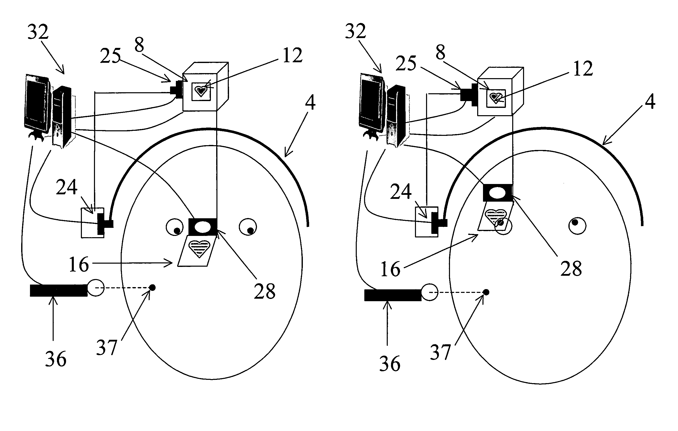
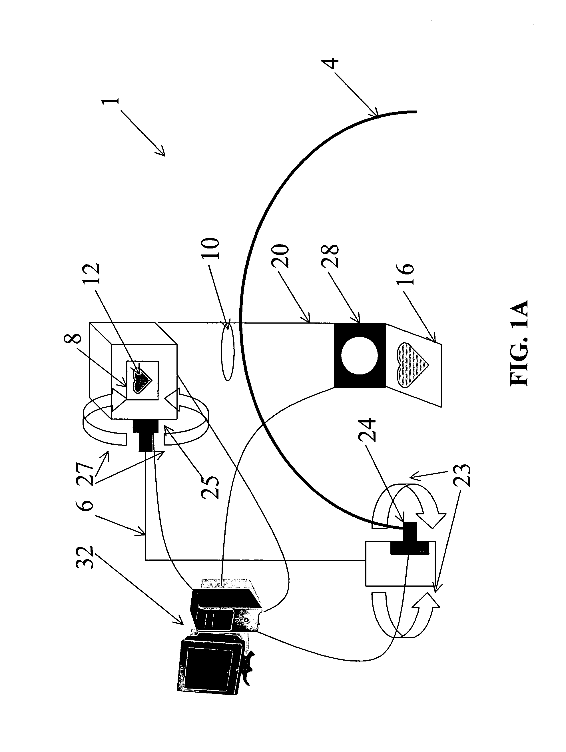
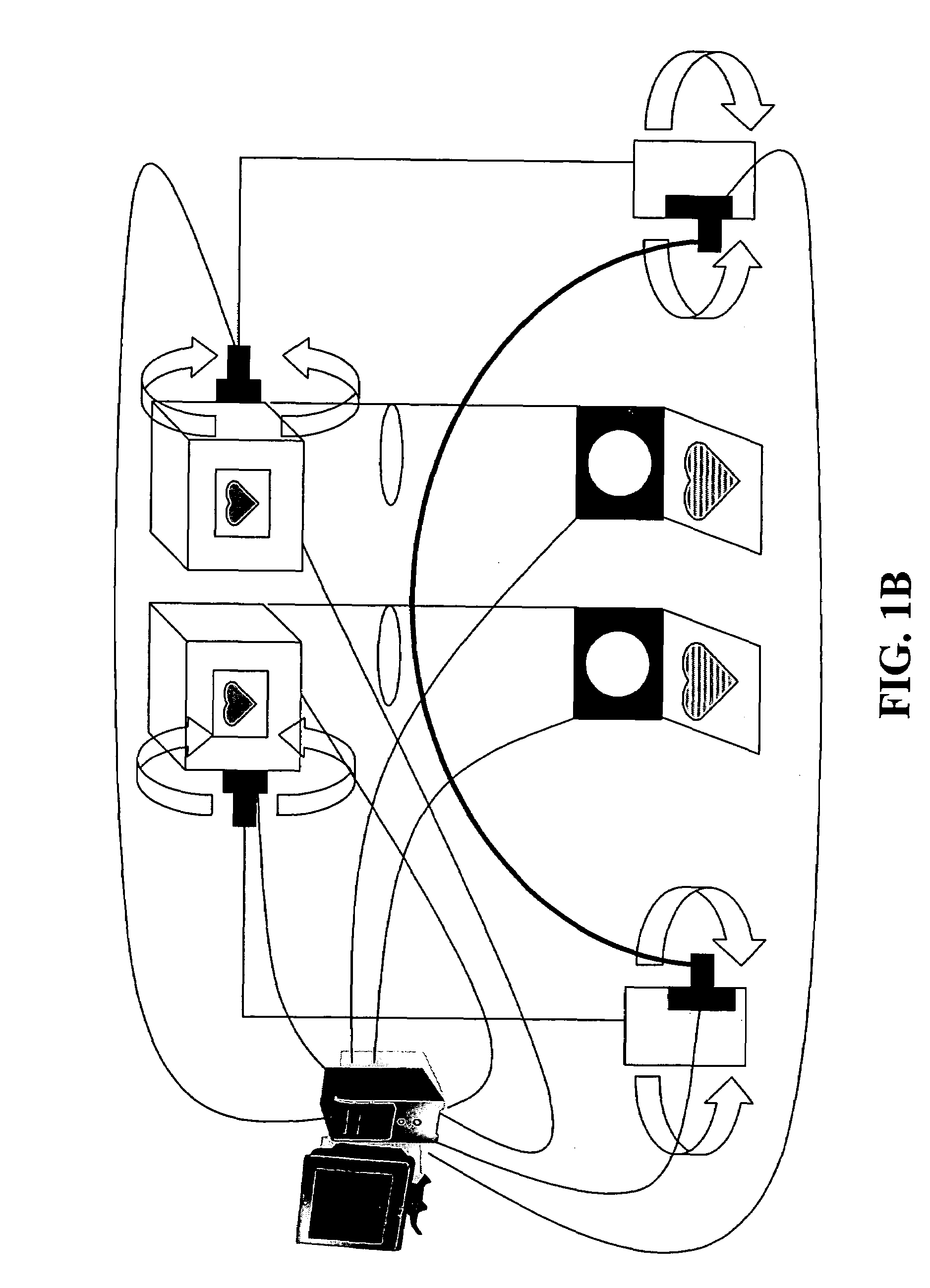
[0048]As shown in FIG. 1A, a mount 4 is provided to connect the HMD 1 to a user. The mount 4 stabilizes the device relative to a user's head. Optionally, it can also allow the device to turn when the user turns his head. A mount can take the form of a hardhat, a helmet, a ball cap or other style of hat, a visor, glasses, goggles, a wire dome, nylon straps, or any other structure that can be secured to a user's head. A good mount provides a sturdy connection to the head while remaining lightweight, comfortable, superposable (capable of being placed over or under additional headwear or head mounts), and easy to put on and take off.

[0049]In FIG. 1A, a projector 8 is attached to the mount 4 by way of a first rigid element 6. The projector produces images 12 which are to be presented to the user. Various types of projectors may be used, including film projectors, digital light projectors, active or passive liquid crystal displays, and any display which can project an image onto a beam-sp...


PUM


Abstract

A head mounted display device has a mount which attaches the device to a user's head, a beam-splitter attached to the mount with movement devices, an image projector which projects images onto the beam-splitter, an eye-tracker which tracks a user's eye's gaze, and one or more processors. The device uses the eye tracker and movement devices, along with an optional head-tracker, to move the beam-splitter about the center of the eye's rotation, keeping the beam-splitter in the eye's direct line-of-sight. The user simultaneously views the image and the environment behind the image. A second beam-splitter, eye-tracker, and projector can be used on the user's other eye to create a stereoptic, virtual environment. The display can correspond to the resolving power of the human eye. The invention presets a high-resolution image wherever the user looks.

Description

FIELD OF THE INVENTION[0001]The present invention relates to head mounted display systems and more particularly, to head mounted display systems which use eye-tracking technology.BACKGROUND OF THE INVENTION[0002]Head mounted display systems (HMDs) are devices, worn on a user's head, which display information to a user. Some HMDs project their display onto large, fixed surfaces in front of a user's eyes. The display surface can be a partially-reflective, partially-transmissive surface, known in the art as a beam-splitter, attached to the user's face and enabling the user to simultaneously view the display and the environment. Alternately, the display surface can be a retro-reflective screen as in U.S. Pat. No. 5,572,229 to Fisher, entitled “Head Mounted Projection Display System Featuring Beam-splitter and Method of Making Same.” Other HMDs use optics (like mirrors and beam-splitters) to project a display directly onto a user's eye.[0003]HMDs are currently used for a wide range of ap...

Claims


Application Information

Patent Timeline
Patent Type & Authority Patents(United States)
IPC IPC(8): G02B27/14G09G5/00
CPCG02B27/0093G02B27/0172G02B2027/011G02B2027/0123G02B2027/0138G02B2027/014G02B2027/0154G02B2027/0187
Inventor CHIRIELEISON, SR., ANTHONY
Owner TEDDER DONALD RAY
Why Eureka
Try Eureka