
Method for operating a converter circuit, and device for carrying out the method

a converter circuit and circuit technology, applied in the field of power electronics, can solve the problems of inability to operate the converter circuit, the switching frequency of the power semiconductor switch is very large, and the conversion circuit described above is subject to the problem, and achieves the effect of simple manner

Inactive Publication Date: 2009-06-02
ABB (SCHWEIZ) AG
View PDF4 Cites 6 Cited by
  • Summary
  • Abstract
  • Description
  • Claims
  • Application Information

AI Technical Summary

Benefits of technology

The patent describes a method and device for operating a converter circuit that can keep the switching frequency of power semiconductor switches constant. This is achieved by using a hysteresis regulator to form a hysteresis signal vector from a difference-phase connection current vector, which is then used to control the power semiconductor switches. The method is simple to implement and can help improve the efficiency and stability of the converter circuit.

Problems solved by technology

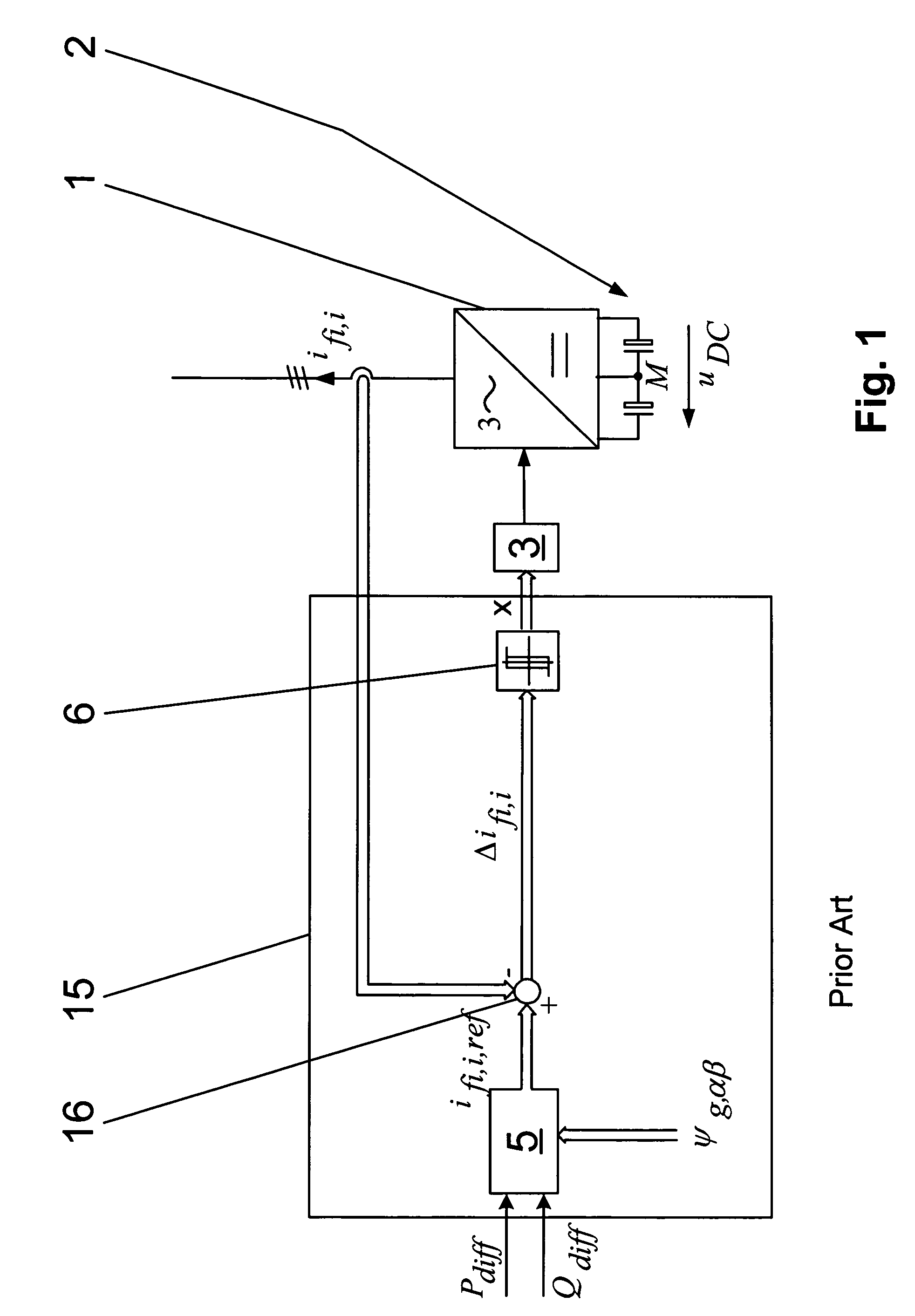
The method for operating a converter circuit described above is subject to the problem that the switching frequency of the power semiconductor switches varies to a very major extent as a result of the formation of the reference phase connection current ifi,i,ref from the reference power value Pref, from the reference wattless component value Qref and from the phase flux vector ψg,αβ.
By way of example, when the converter circuit is connected to an electrical interconnected power supply system, such high harmonic components are undesirable or are unacceptable.
For example, when the converter circuit is connected to an electrical load, harmonics such as these can lead to damage or even destruction, and are therefore very highly undesirable.

Method used


Image

  • Method for operating a converter circuit, and device for carrying out the method
  • Method for operating a converter circuit, and device for carrying out the method
  • Method for operating a converter circuit, and device for carrying out the method

Examples


Embodiment Construction

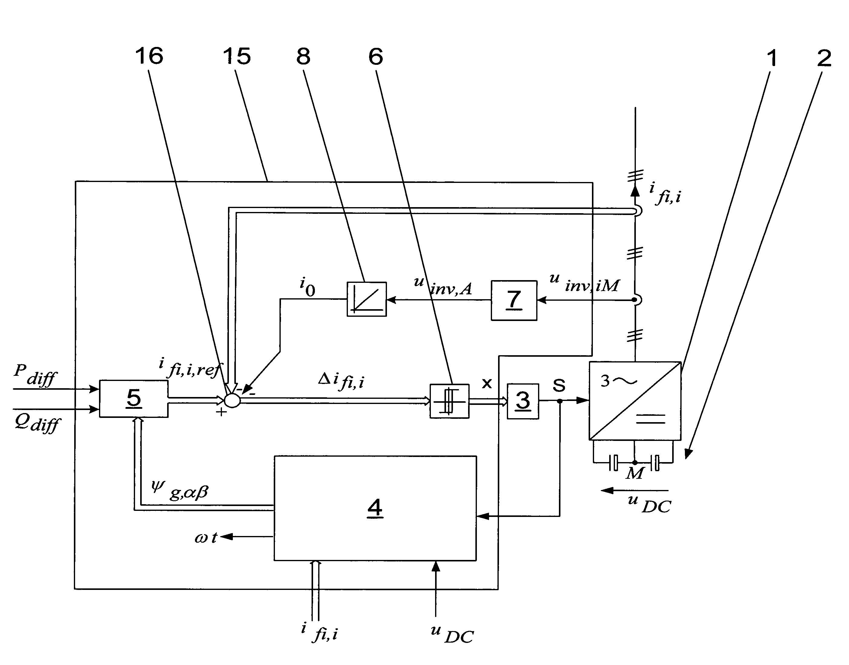
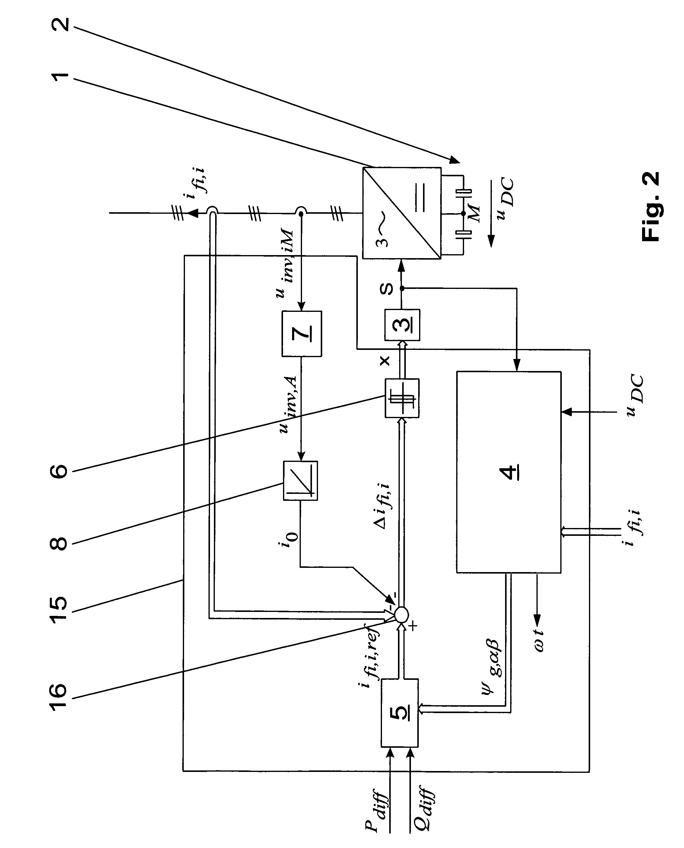
[0017]The converter circuit has a converter unit with a multiplicity of controllable power semiconductor switches, and an energy storage circuit formed by two series-connected capacitors. In the method according to the disclosure for operating the converter circuit, the controllable power semiconductor switches are now controlled by means of a control signal which is formed from a hysteresis signal vector, with the hysteresis signal vector being formed from a difference-phase connection current vector by means of a hysteresis regulator, and with the difference-phase connection current vector being formed from the subtraction of a phase connection current vector from a reference phase connection current vector. The reference phase connection current vector is furthermore formed from a reference power value, a reference wattless component value and a phase flux vector. According to the disclosure, a current correction value is additionally subtracted in order to form the difference-ph...


PUM


Abstract

A method for operating a converter circuit is specified with the converter circuit having a converter unit with a multiplicity of controllable power semiconductor switches and having an energy storage circuit formed by two series-connected capacitors, in which the controllable power semiconductor switches are controlled by means of a control signal formed from a hysteresis signal vector (x), and the hysteresis signal vector (x) is formed from a difference-phase connection current vector (Δifi,i) by means of a hysteresis regulator, and the difference-phase connection current vector (Δifi,i) is formed from the subtraction of a phase connection current vector (ifi,i) from a reference phase connection current vector (ifi,i,ref), with the reference phase connection current vector (ifi,i,ref) being formed from a difference power value (Pdiff), a difference wattless-component value (Qdiff) and a phase flux vector (ψg,αβ). In order to very largely stabilize the switching frequency of the controllable power semiconductor switches, a current correction value (i0) is additionally subtracted in order to form the difference-phase connection current vector (Δifi,i), with the current correction value (i0) being formed by integration of a phase connection voltage mean value (uinv,A), and the phase connection voltage mean value (uinv,A) being formed by determining the arithmetic mean value of the phase connection voltages (uinv,iM) with the reference point of the connection point of the capacitors in the energy storage circuit. A device is also specified, by means of which the method can be carried out in a particularly simple manner.

Description

RELATED APPLICATIONS[0001]This is a continuation application under 35 U.S.C. §120 of PCT / CH2006 / 000648 filed as an International Application on Nov. 16, 2006 designating the U.S., which claims the benefit of U.S. Provisional Patent No. 60 / 738,065 filed on Nov. 21, 2005, under 35 U.S.C. 365(c), the entire contents of which are hereby incorporated by reference in their entireties.TECHNICAL FIELD[0002]The disclosure relates to the field of power electronics, and in particular to a method for operating a converter circuit, and to an device for carrying out the method.BACKGROUND INFORMATION[0003]Conventional converter circuits have a converter unit with a multiplicity of controllable power semiconductor switches, which are switched in a known manner in order to switch at least two switching voltage levels. Furthermore, by way of example, an LCL-filter can be connected to each phase connection of the converter unit. FIG. 1 shows one embodiment of a device for carrying out a method for ope...

Claims


Application Information

Patent Timeline
Patent Type & Authority Patents(United States)
IPC IPC(8): H02M1/12H02M7/527
CPCH02M1/12H02M7/219
Inventor SERPA, LEONARDOKOLAR, JOHANN WALTERROUND, SIMON DOUGLAS
Owner ABB (SCHWEIZ) AG
Learn More