X-ray CT apparatus

a computed tomography and x-ray technology, applied in tomography, instruments, applications, etc., can solve problems such as difficult separation, and achieve the effect of reducing the influence of scattered radiation

Inactive Publication Date: 2009-06-02
KK TOSHIBA +1
View PDF14 Cites 7 Cited by
  • Summary
  • Abstract
  • Description
  • Claims
  • Application Information

AI Technical Summary

Benefits of technology

[0008]It is an object of the present invention to reduce the influence of scattered radiation originating from X-rays from the X-ray tube of the other pair in an multi-tube type X-ray CT apparatus including a plurality of pairs of X-ray tubes and detectors.
[0009]According to a first aspect of the present invention, there is provided an X-ray CT apparatus comprising a plurality of X-ray tubes, a plurality of slit mechanisms which are respectively provided for the plurality of X-ray tubes and whose slit widths are adapted to be changed, a plurality of X-ray detectors which form pairs with the plurality of X-ray tubes, each X-ray detector including a plurality of detection elements arrayed in a matrix form in a channel direction and a slice direction, a support mechanism which supports the X-ray tubes and the X-ray detectors so as to allow the X-ray tubes and the X-ray detectors to rotate about a rotation axis parallel to the slice direction, a correction unit which corrects data from each detection element located in an area which X-rays passing through the slit mechanism directly strike, by using data from at least one detection element located outside the area and associated with the same channel in order to reduce a scattered radiation component originating from X-rays generated by an X-ray tube other than the X-ray tube forming the pair, and a reconstruction unit which reconstructs image data on the basis of the corrected data.

Problems solved by technology

In addition, since direct radiation does not differ much in characteristics from scattered radiation, it is difficult to separate them.

Method used


Image

  • X-ray CT apparatus
  • X-ray CT apparatus
  • X-ray CT apparatus

Examples


Embodiment Construction

[0023]An embodiment of the present invention will be described below in detail with reference to the views of the accompanying drawing.

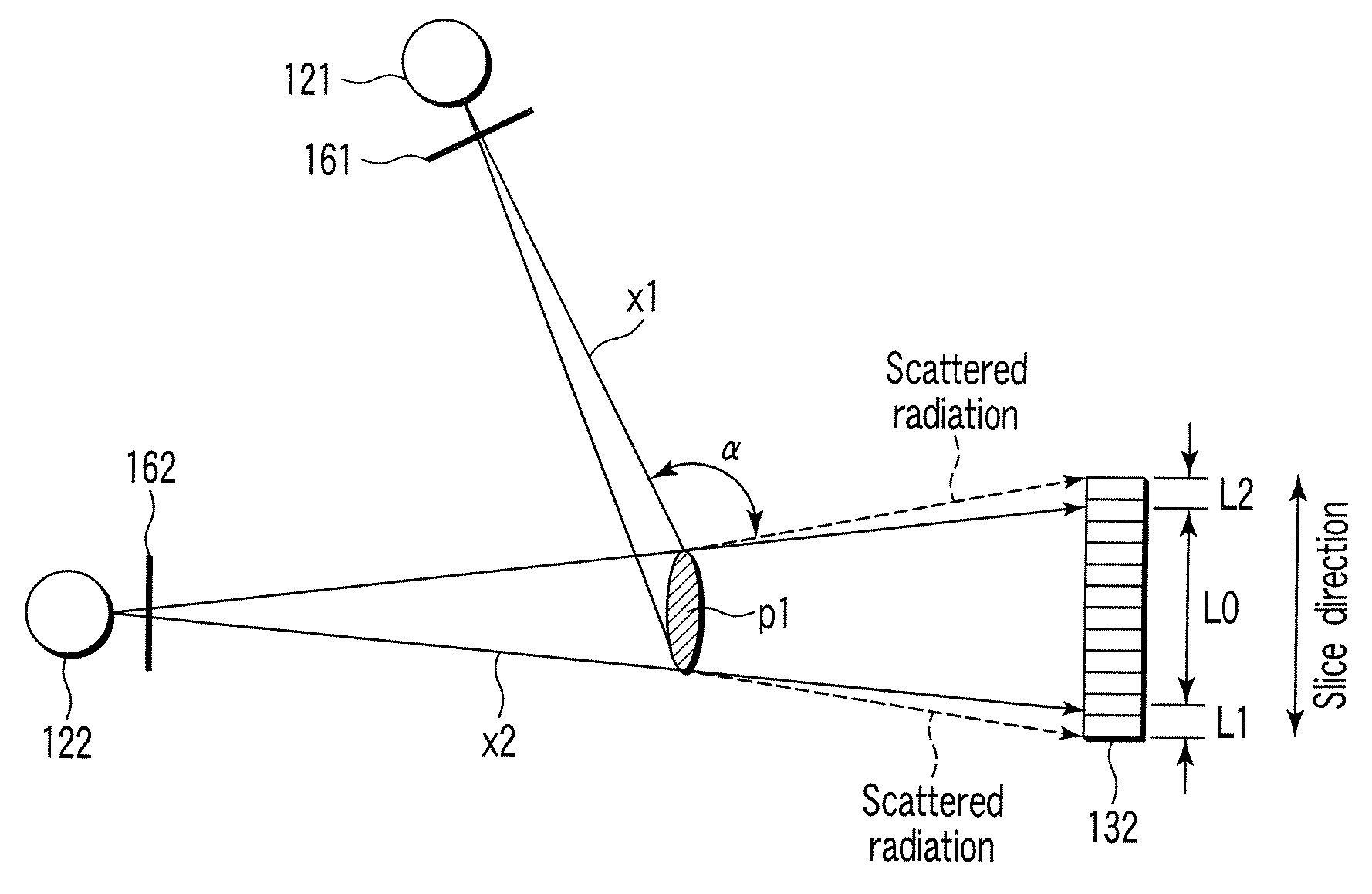
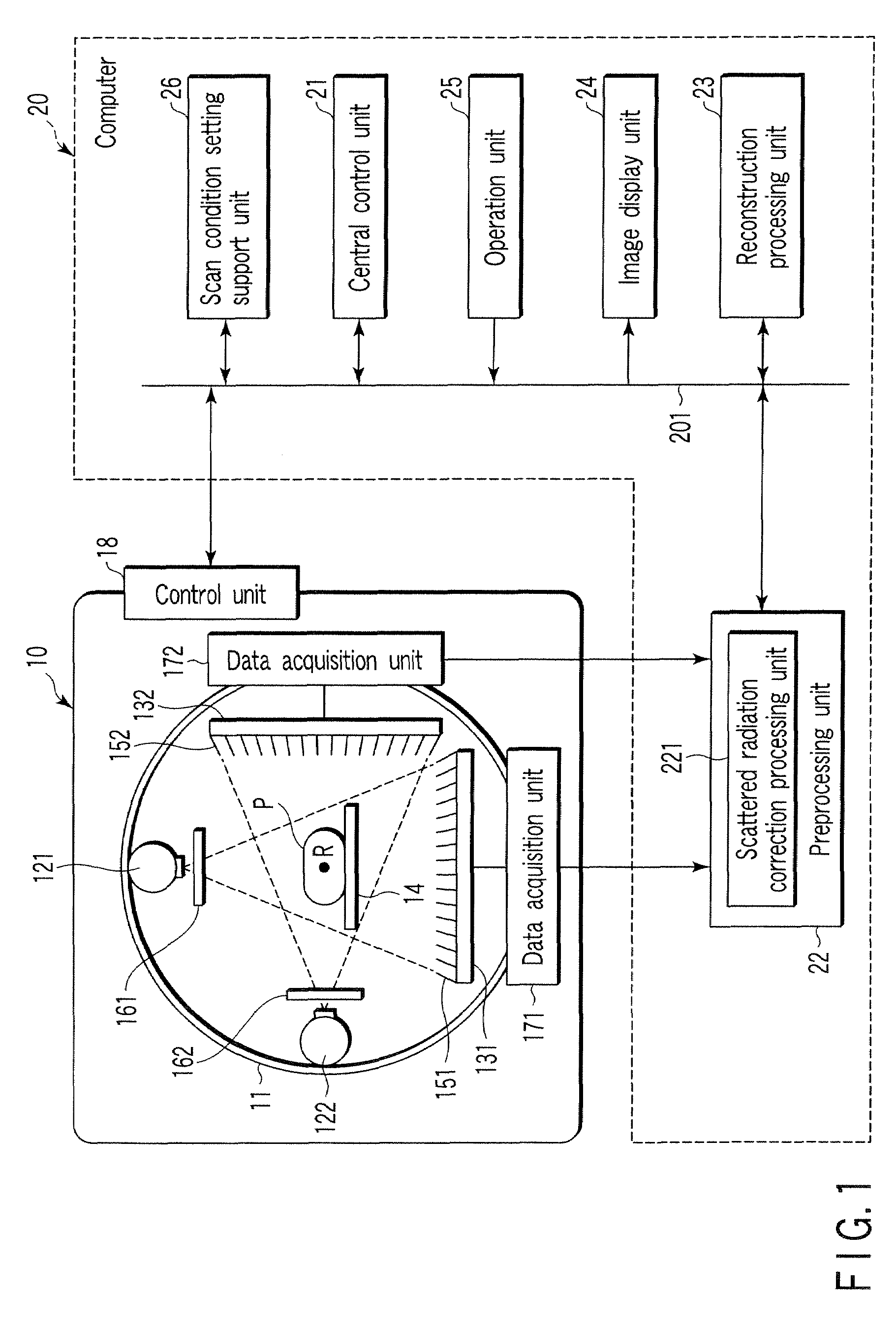
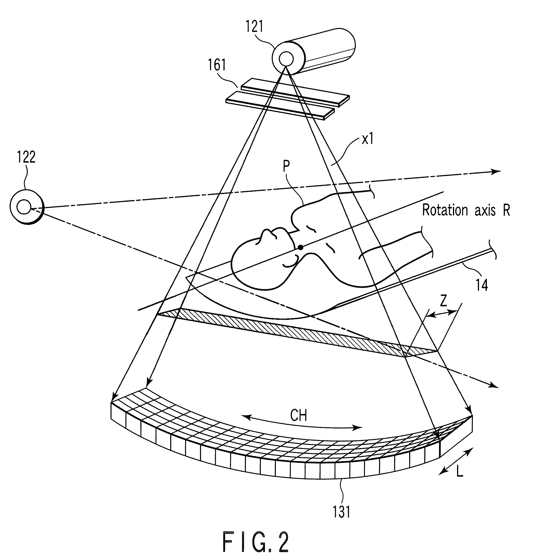
[0024]FIG. 1 is a block diagram showing the overall arrangement of an X-ray CT apparatus according to an embodiment of the present invention. Referring to FIG. 1, the X-ray CT apparatus (X-ray computed tomography apparatus) of this embodiment includes a gantry 10, a computer 20, and a bed (not shown). The gantry 10 is of a multi-tube type, on which a plurality of pairs of X-ray tubes and X-ray detectors are mounted. In this embodiment, this gantry will be described as a two-tube type gantry.

[0025]The gantry 10 is provided with a rotating frame 11. The rotating frame 11 rotates about a rotation axis R by a rotating mechanism (not shown). The first pair of an X-ray tube 121 and an X-ray detector 131 and the second pair of an X-ray tube 122 and an X-ray detector 132 are mounted on the rotating frame 11. The imaging axis of the first pair intersects the ...


PUM


Abstract

An X-ray CT apparatus includes X-ray tubes, slit mechanisms which are respectively provided for X-ray tubes and whose slit widths can be changed, two-dimensional array type X-ray detectors which form pairs with the X-ray tubes, a support mechanism which supports the X-ray tubes and the X-ray detectors so as to allow them to rotate about a rotation axis parallel to the slice direction, a correction unit which corrects data from each detection element located in an area which X-rays passing through the slit mechanism directly strike, by using data from at least one detection element located outside the area and associated with the same channel in order to reduce a scattered radiation component originating from X-rays generated by an X-ray tube other than the X-ray tube forming the pair, and a reconstruction unit which reconstructs image data on the basis of the corrected data.

Description

CROSS-REFERENCE TO RELATED APPLICATIONS[0001]This application is based upon and claims the benefit of priority from prior Japanese Patent Application No. 2005-206873, filed Jul. 15, 2005, the entire contents of which are incorporated herein by reference.BACKGROUND OF THE INVENTION[0002]1. Field of the Invention[0003]The present invention relates to a multi-tube type X-ray computed tomography (CT) apparatus comprising a plurality of pairs of X-ray tubes and detectors.[0004]2. Description of the Related Art[0005]Conventionally, an X-ray CT apparatus is designed to apply X-rays generated by an X-ray tube to a subject to be examined and detect X-rays transmitted through the subject by using an X-ray detector, thereby obtaining a tomogram by performing reconstruction processing for detected data using a computer. A multi-tube type X-ray CT apparatus is also known, in which two or more pairs of X-ray tubes and detectors are mounted on an annular rotating frame to reduce the rotation angle...

Claims


Application Information

Patent Timeline
Patent Type & Authority Patents(United States)
IPC IPC(8): A61B6/03
CPCA61B6/032A61B6/4014A61B6/5282
Inventor MATSUDA, KEIJI
Owner KK TOSHIBA
Why Eureka
Try Eureka