Brake rotor assembly

a rotor and brake technology, applied in the direction of brake elements, brake discs, brake types, etc., can solve the problems of high thermal load, grey cast iron tends to fracture, etc., and achieve the effect of high tensile strength and maximum contact area between the friction disc and the brake pad

Inactive Publication Date: 2009-06-09
BWI CO LTD SA
View PDF18 Cites 24 Cited by
  • Summary
  • Abstract
  • Description
  • Claims
  • Application Information

AI Technical Summary

Benefits of technology

[0011]Accordingly, the subject invention provides an improved composite brake rotor assembly suitable for use in a dual disc braking system. The high tensile strength material, having a tensile strength greater than 260 megapascals and forming the annular ring and the plurality of teeth, permit the brake rotor assembly to resist fracture under high stress braking conditions and high thermal loads. Additionally, the contact area between the friction disc and the brake pads is maximized by casting the friction disc around the annular ring instead of bolting the annular ring to the friction disc. The casting of the friction disc around the annular ring permits the contact area to extend all the way to the annular ring adjacent the plurality of teeth, without loosing any of the contact area to a bolted connection connecting the annular ring to the friction disc.

Problems solved by technology

However, the grey cast iron tends to fracture under certain high stress braking conditions and high thermal loads generated by the frictional engagement between the brake pads and the brake disc.
Additionally, the grey cast iron tends to corrode at the toothed engagement between the teeth of the brake rotor and the groove in the hub, thereby bonding the brake rotor to the hub.

Method used


Image

  • Brake rotor assembly
  • Brake rotor assembly
  • Brake rotor assembly

Examples


Embodiment Construction

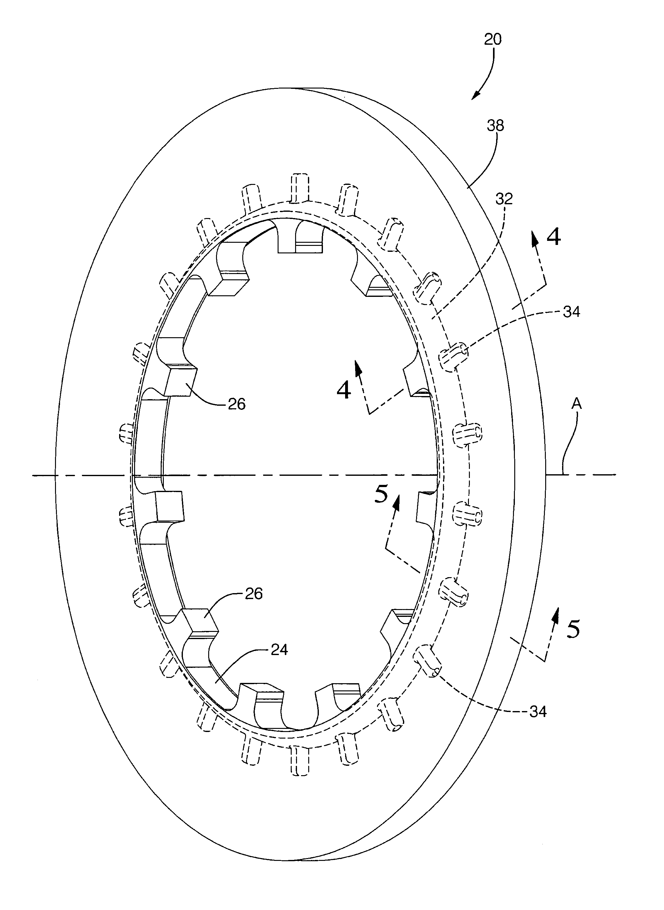
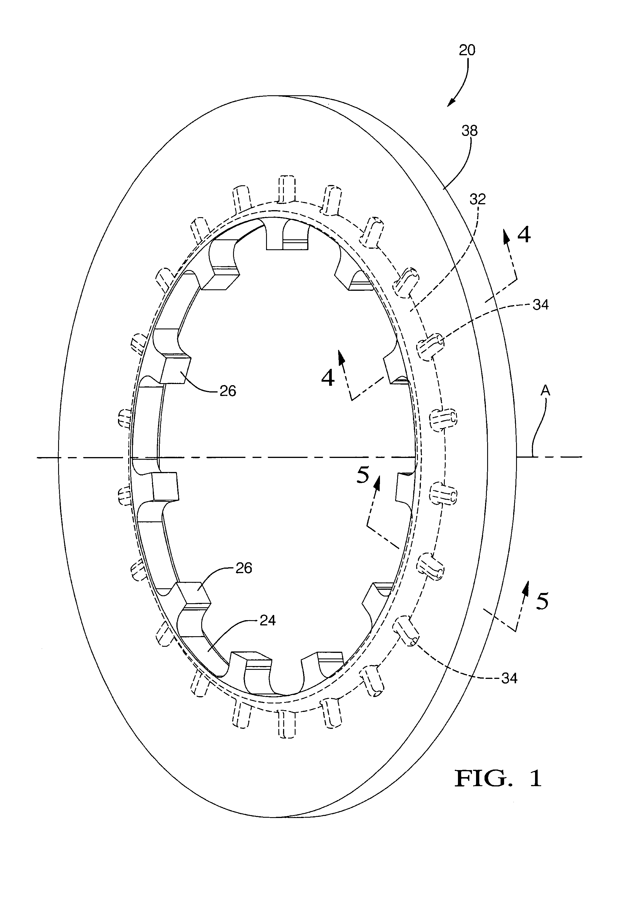
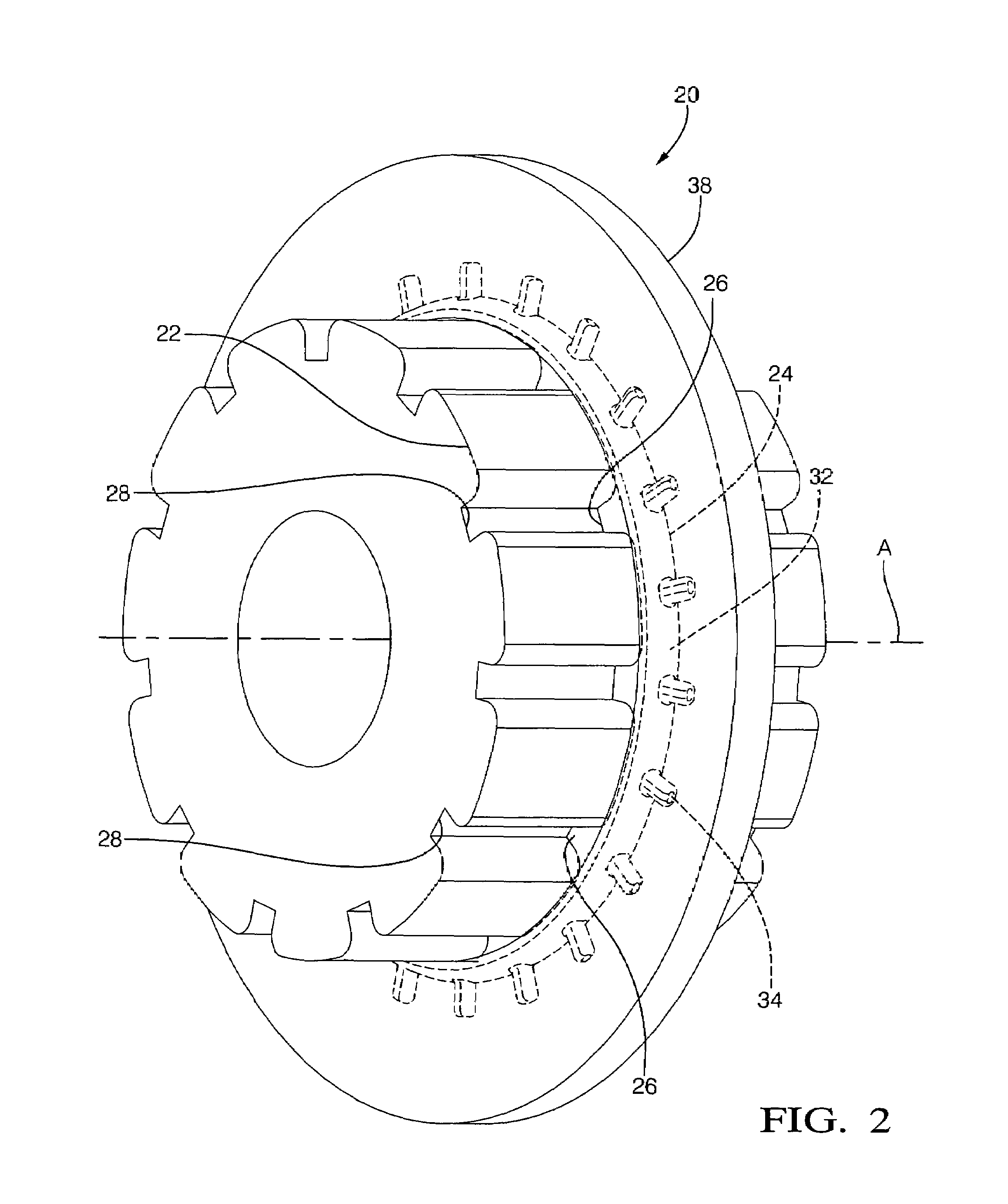
[0019]Referring to the Figures, wherein like numerals indicate corresponding parts throughout the several views, a brake rotor assembly is generally shown at 20 in FIGS. 1 and 2. The brake rotor assembly 20 is utilized in a disc braking system for a vehicle. The disc braking system operates as is known in the art, and includes a brake caliper (not shown) for urging a pair of brake pads (not shown) into frictional engagement with the brake rotor assembly 20. The brake rotor assembly 20 is mounted to a hub 22 (wheel end or axle) by a splined connection as described below for rotation with the hub 22. As is known with the disc braking system, the frictional engagement between the brake rotor assembly 20 and the brake pads supply a stopping force, transmitted through the brake rotor assembly 20 to the hub 22, to slow the vehicle.

[0020]The brake rotor assembly 20 includes an annular ring 24. The annular ring 24 includes a plurality of teeth 26 extending inwardly toward a central axis A, ...


PUM


Abstract

A brake rotor assembly for a dual brake disc braking system includes an annular ring having a plurality of teeth. The teeth are disposed radially about a central axis of the annular ring, and extend inward toward the central axis. The teeth are for slideably engaging a hub (wheel end) having a plurality of channels. The annular ring includes a plurality of pins extending outwardly from the annular ring. A friction disc is disposed radially about the annular ring, and is in interlocking engagement with the plurality of pins. The annular ring and the plurality of teeth are integrally cast from a high strength corrosion resistant material having a tensile strength greater than 260 megapascals to resist fracture during high stress braking conditions and high thermal loads. The friction disc is cast around the annular ring from a grey cast iron.

Description

BACKGROUND OF THE INVENTION[0001]1. Field of the Invention[0002]The subject invention relates to a brake rotor assembly for a disc braking system of a vehicle, and further relates to a method of producing the brake rotor assembly.[0003]2. Description of the Prior Art[0004]Disc braking systems for vehicles utilize a brake caliper to urge a pair of brake pads into frictional engagement with a brake rotor (brake disc) to provide a braking force to the vehicle. In order to increase the braking force applied by the disc braking system, it is known to incorporate a second brake rotor into the disc braking system. This may be referred to as a dual disc braking system. The dual disc braking system necessitates that a first brake rotor be slideable along a central axis relative to a second brake rotor. The first brake rotor slides over and rotates with a hub (wheel end or axle). The slideable first brake rotor compensates for wear in the brake pads over time. Accordingly, as the brake pads w...

Claims


Application Information

Patent Timeline
Patent Type & Authority Patents(United States)
IPC IPC(8): F16D65/12
CPCF16D65/12F16D2065/1316F16D2065/1344F16D2065/1368
Inventor HOPKINS, EUNJOO C.HOPKINS, PATRICK N.VALVANO, THOMAS V.LIMPACH, JEROME A.JESME, ERIC W
Owner BWI CO LTD SA
Why Eureka
Try Eureka