Relay circuitry and switching circuitry for power-over-network devices
- Summary
- Abstract
- Description
- Claims
- Application Information
AI Technical Summary
Benefits of technology
Problems solved by technology
Method used
Image
Examples
Embodiment Construction
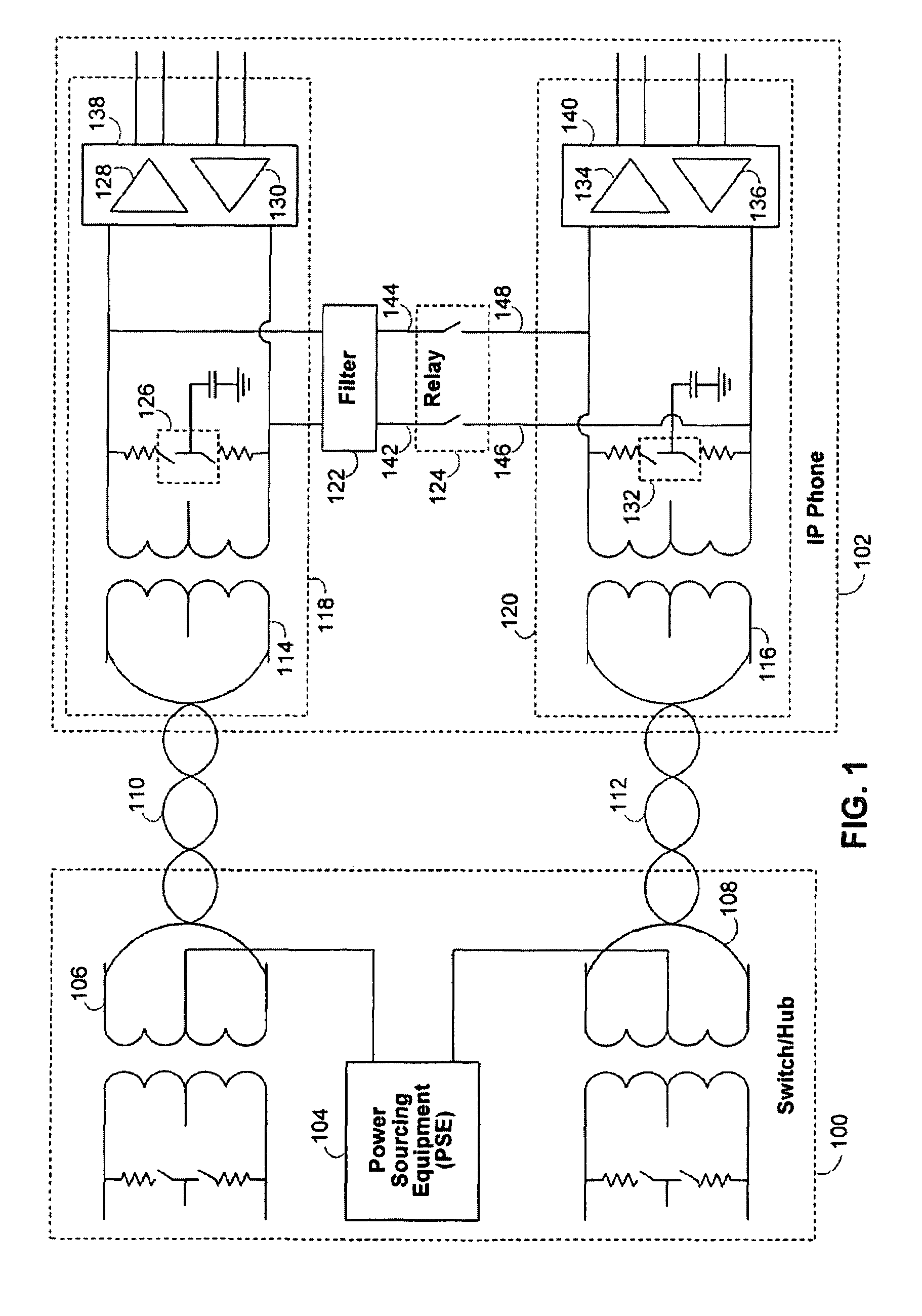
[0011]FIG. 1 shows an illustrative embodiment of a typical system in which the circuitry of the present invention is implemented. In FIG. 1, power-supplying network device 100 (such as a switch or a hub) is connected to an Ethernet network to which power-over-network device 102 (such as an Internet Protocol (“IP”) telephone) is connected. Although references are made herein to an Ethernet network, such references are merely the purpose of illustration, and it will therefore be understood that the present invention may be realized in other suitable types of networks. Specifically, in FIG. 1, power-supplying network device 100 includes power-sourcing equipment (“PSE”) 104 that is connected to the center taps in the primary side of each of power transformers 106 and 108. As a result, the power provided by PSE 104 is supplied over Ethernet links 110 and 112 to the secondary sides of power transformers 114 and 116, which are in turn connected to power-over-network device 102.
[0012]The po...
PUM
| Property | Measurement | Unit |
|---|---|---|
| Power | aaaaa | aaaaa |
| Current | aaaaa | aaaaa |
Abstract
Description
Claims
Application Information
 - R&D Engineer
- R&D Manager
- IP Professional
- Industry Leading Data Capabilities
- Powerful AI technology
- Patent DNA Extraction
Browse by: Latest US Patents, China's latest patents, Technical Efficacy Thesaurus, Application Domain, Technology Topic, Popular Technical Reports.
© 2024 PatSnap. All rights reserved.Legal|Privacy policy|Modern Slavery Act Transparency Statement|Sitemap|About US| Contact US: help@patsnap.com


