Bandless halftone design for multiple beam printers employing non-orthogonal halftones

a technology of halftones and printers, applied in the field of printing systems, can solve the problems of easily detectable banding and affected banding in multiple beam printers

Inactive Publication Date: 2009-06-09
INFOPRINT SOLUTIONS COMPANY LLC
View PDF20 Cites 2 Cited by
  • Summary
  • Abstract
  • Description
  • Claims
  • Application Information

AI Technical Summary

Benefits of technology

[0009]The identified object is achieved by a printer system that includes a controller to receive print job information from a print host and a rendering application to generate halftone image data from the print job. Imaging hardware, including multiple laser beams, is configured to print N lines of a document simultaneously as in a raster. A laser source is described, however other light sources, such as light Emitting Diodes, can be used to create multiple light sources imaging N lines of a document simutaneously. The rendering application uses a threshold array based on a defined screen dot to generate the halftone image data. The defined screen dot may be orthogonal or non-orthogonal and includes Y pels in a direction that is perpendicular to a raster direction of the laser beams where Y is an integer multiple of N. The distance between adjacent screen dots in pels may be equal to N or a multiple of N. Depending on the screen parameters, in a preferred embodiment the threshold array is composed of supercell tiling of a basic supercell encompassing two screen dots and having an odd number of pels in a direction that is parallel to the raster direction. In an alternative embodiment, the basic cell consists of a single screen dot. The screen dot may be defined with the use of a spot function halftone. In cases where the basic cell encompasses multiple screen dots, the spot function includes a snap feature that snaps a screen dot to the nearest printer grid pel. The spot function may be scaled linearly in one direction by the non-orthogonal screen dot. The direction of linear scaling in the spot function is preferably the direction of greater ellipticity as that could provide continuity between adjacent dots. Alternatively, the spot function may also be spatially scaled with a factor that depends on its distance to the center of the cell. This results in more scaling near the center of the cell to compensate for the distortion brought on by the non-orthogonality of the screen dot, with the scaling continuously reducing to no scaling at the boundary of the screen cell, thus insuring continuity between adjacent dots.

Problems solved by technology

Banding in multiple beam printers is affected by differences in the power of individual laser beams, scan direction beam offsets, and spot spacing errors.
Unfortunately, the spatial frequency for banding is often near the most sensitive region of human perception and, accordingly, very small errors of any of these parameters can result in easily detectable banding.

Method used


Image

  • Bandless halftone design for multiple beam printers employing non-orthogonal halftones
  • Bandless halftone design for multiple beam printers employing non-orthogonal halftones
  • Bandless halftone design for multiple beam printers employing non-orthogonal halftones

Examples


Embodiment Construction

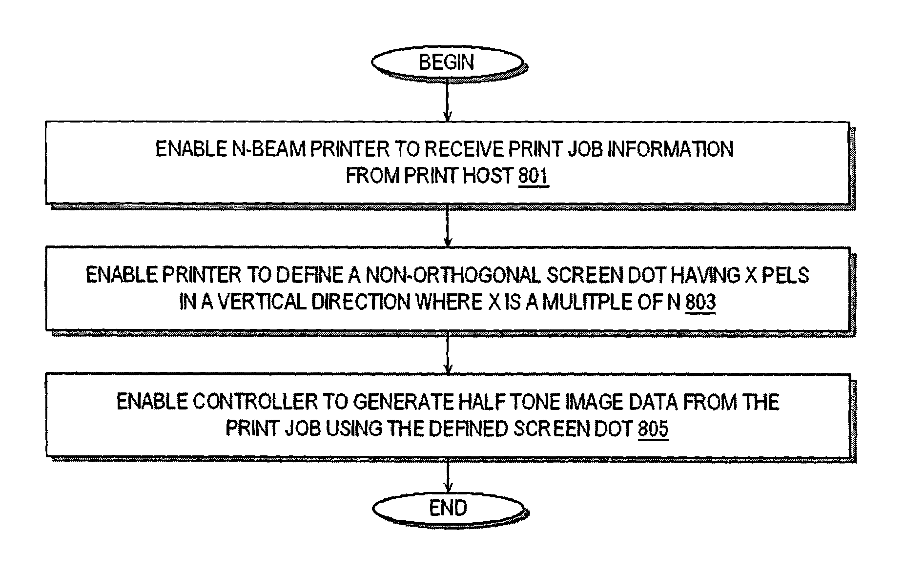
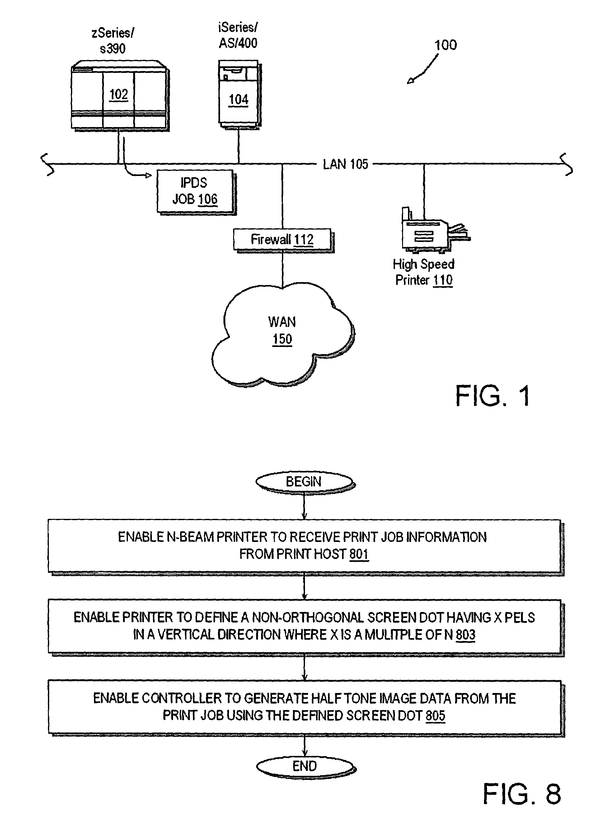
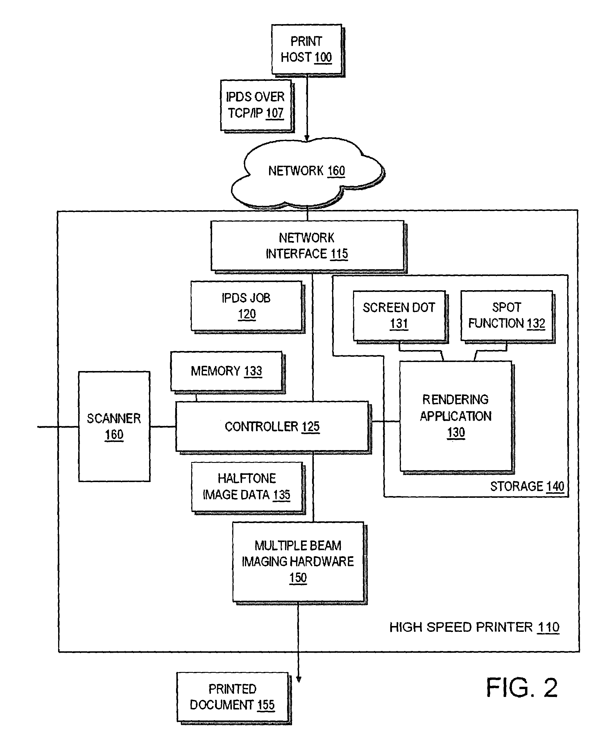
[0023]Generally speaking, the invention is directed towards a multiple beam printer system that produces substantially bandless halftone images. The printer system employs N laser beams and uses an X x Y halftone supercell design where X is the number of pels in the horizontal direction (HSIDE) and Y is the number of pels in the vertical direction (VSIDE). Preferably, Y is an integer multiple of N such that the distance between halftone screen dots is equal to an integer multiple of the total distance between all the beams of the multiple beam raster. Embodiments of the invention may employ a non-orthogonal screen dot supercell where the supercell defines two or more screen dots. The supercell may have an odd number of pels in either the horizontal or vertical direction. For supercells with an odd number of HSIDE or VSIDE pels, the invention preferably uses a spot function and an associated snap that function causes each screen dot in the supercell to grow consistently from all whit...


PUM


Abstract

A multiple beam printer system having N laser beams receives print job information from a print host. A rendering application uses a threshold array to generate halftone image data from the print job. The threshold array is defined based on a spot function. The defined screen is non-orthogonal and includes Y pels in a direction that is perpendicular to a scanning direction of the laser beams where Y is an integer multiple of N. A distance between screen dots in pels is preferably equal to an integer multiple of N. The screen dot may be defined by a supercell encompassing two screen dots and having an odd number of pels in a direction that is parallel to the scanning direction. The spot function may include a snap feature that snaps a screen dot to the nearest printer grid pel. The spot function may include scaling to compensate for the distortion of the non-orthogonal screen dot.

Description

BACKGROUND[0001]1. Field of the Present Invention[0002]The present invention is in the field of printer systems and more particularly, printer systems employing multiple beams.[0003]2. History of Related Art[0004]A halftone image is a reproduction of a contone image (e.g., a photograph), using spots of varying size to produce apparent shades of gray. The darker the shade at a particular point in the image, the larger the corresponding spot in the halftone. In traditional publishing, halftones are created by photographing an image through a screen. In desktop publishing, each halftone spot is created by a collection of darkened pixels printed by a laser printer or digital image setter. In the case where the halftone spots form a regular grid the frequency of the halftone dots is measured in lines per inch. Higher printer resolution enables effective use of higher density of halftone dots, enhancing image quality.[0005]An image typically is an array of values created by scanning a con...

Claims


Application Information

Patent Timeline
Patent Type & Authority Patents(United States)
IPC IPC(8): G06K15/00H04N1/405
CPCH04N1/4055
Inventor LI, HONGSTANICH, MIKEL JOHNTHOMPSON, GERHARD ROBERTWU, CHAI WAH
Owner INFOPRINT SOLUTIONS COMPANY LLC
Why Eureka
Try Eureka