Scanning unit and image forming apparatus

a scanning unit and image forming technology, applied in the field of scanning units, can solve the problems of increasing noise and power consumption, reducing the durability of polygon scanning, and difficulty in coupling lenses,

Active Publication Date: 2009-06-09
RICOH KK
View PDF23 Cites 37 Cited by
  • Summary
  • Abstract
  • Description
  • Claims
  • Application Information

AI Technical Summary

Problems solved by technology

However, if the polygon scanner is rotated a high speed, noise and power consumption increases and durability of the polygon scanner drops.
In the scheme (1), a low price can be realized because general-purpose lasers can be used, but using a plurality of beams to stably maintain a relative positional relationship between the lasers and a coupling lens is difficult, and an interval between a plurality of scan lines formed on a scanning target surface (hereinafter, “scan line interval”) may possibly become uneven.
Further, in the scheme (1), the number of light sources practically has a limit, and the density growth and the increase in speed also have limits.
In the scheme (2), an even scan line interval can be formed, but this scheme has a disadvantage that a power consumption of an element is increased.
Furthermore, when the number of light sources is extremely increased, a displacement amount of each beam from an optical axis of an optical system is increased, and a so-called beam quality may be degraded.

Method used


Image

  • Scanning unit and image forming apparatus
  • Scanning unit and image forming apparatus
  • Scanning unit and image forming apparatus

Examples


Embodiment Construction

[0039]Exemplary embodiments of the present invention will now be explained hereinafter with reference to accompanying drawings.

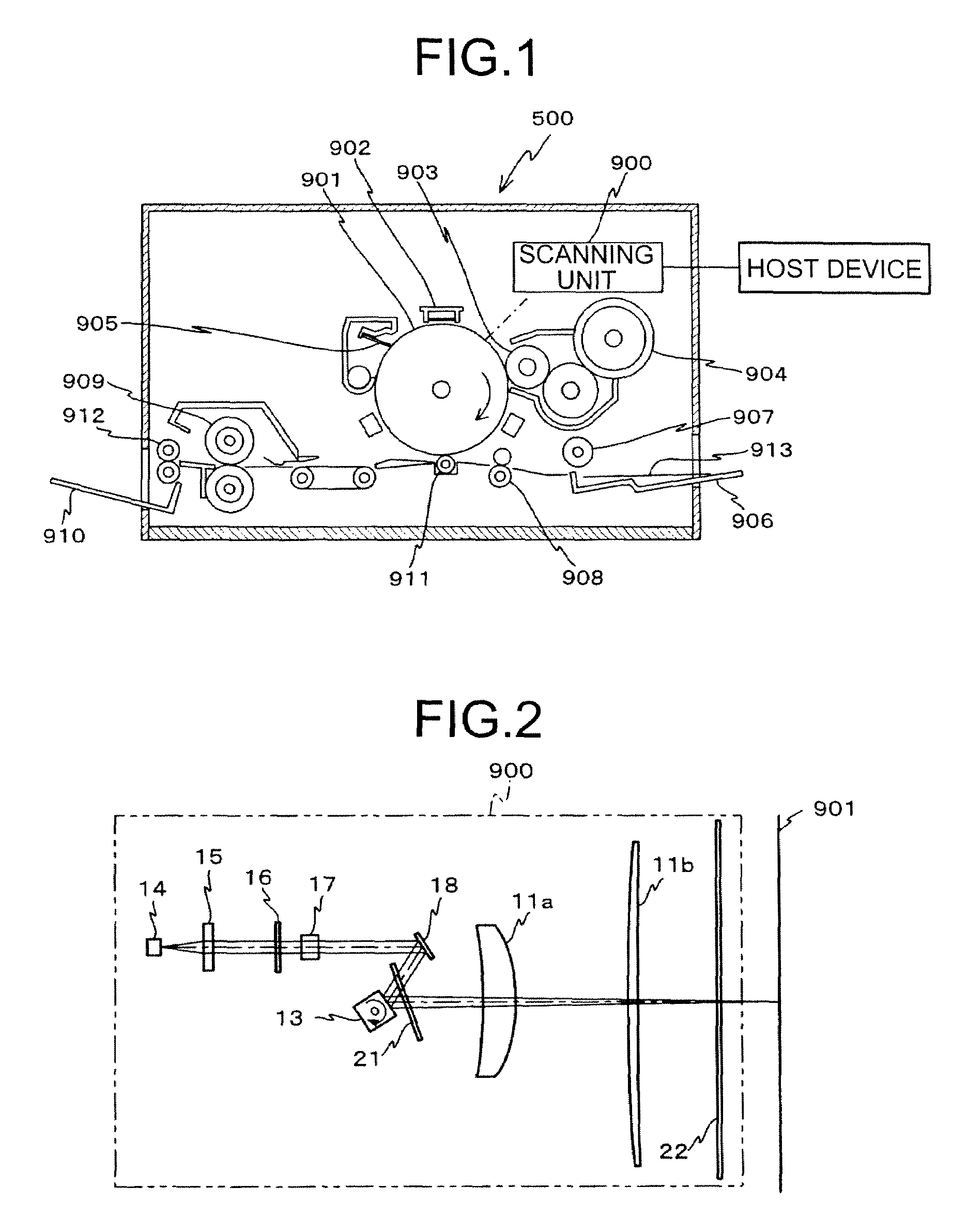
[0040]FIG. 1 depicts a laser printer 500 according to an embodiment of the present invention. The laser printer 500 includes a scanning unit 900, a photosensitive drum 901, an electrostatic charger 902, a developing roller 903, a toner cartridge 904, a cleaning blade 905, a paper feed tray 906, a paper feed runner 907, a pair of registration rollers 908, a transfer charger 911, a fixing roller 909, a pair of paper ejection rollers 912, a paper ejection tray 910.

[0041]The electrostatic charger 902, the developing roller 903, the transfer charger 911, and the cleaning blade 905 are arranged around and near the periphery of the photosensitive drum 901. The electrostatic charger 902, the developing roller 903, the transfer charger 911, and the cleaning blade 905 are arranged in this order along the direction of rotation (direction indicted by an arrow in FIG. 1)...


PUM


Abstract

A scanning optical system leads the light fluxes deflected by the polygon mirror to a photosensitive drum. An absolute value of a lateral magnification in a main scanning direction is larger than an absolute value of a lateral magnification in a sub-scanning direction. Moreover, a beam diameter in the sub-scanning direction on a surface of the photosensitive drum is equal to or smaller than a beam diameter in the main scanning direction and larger than a scan line interval.

Description

CROSS-REFERENCE TO RELATED APPLICATIONS[0001]The present application claims priority to and incorporates by reference the entire contents of Japanese priority document, 2006-290030 filed in Japan on Oct. 25, 2006.BACKGROUND OF THE INVENTION[0002]1. Field of the Invention[0003]The present invention generally relates to a scanning unit, and specifically relates to an optical scanning unit for use in an image forming apparatus.[0004]2. Description of the Related Art[0005]Image forming apparatuses that employ laser are being widely used for printing electronic images. Such an image forming apparatus typically includes a scanning unit and a photosensitive drum. The scanning unit includes a polygon scanner (e.g., a polygon mirror) that deflects laser toward the photosensitive drum, which is rotating, thereby scanning the surface of the photosensitive drum with the laser. Due to such scanning, a latent image is formed on the surface of the photosensitive drum. In image forming apparatuses,...

Claims


Application Information

Patent Timeline
Patent Type & Authority Patents(United States)
IPC IPC(8): G02B26/08
CPCG02B26/124G02B26/125
Inventor HAYASHI, YOSHINORIKUBO, NOBUAKIWATANABE, NAOTOICHII, DAISUKE
Owner RICOH KK
Why Eureka
Try Eureka