Exposure head

a technology of exposure head and head, which is applied in the direction of microlithography exposure apparatus, photomechanical treatment, instruments, etc., can solve the problems of insufficient effect of reducing cross-talk light and scattered light, difficult to achieve a balance between light use efficiency and obtaining uniform exposure spots at the exposure plane,

Active Publication Date: 2005-02-03
ADTEC ENG +1
View PDF6 Cites 31 Cited by
  • Summary
  • Abstract
  • Description
  • Claims
  • Application Information

AI Technical Summary

Problems solved by technology

However, in this optical system, there are the problems that a trade-off is necessary between the uniformity of the illumination of the microlens apertures and the suppression of cross-talk of adjacent apertures, and it is difficult to achieve a balance between light use efficiency and obtaining uniform exposure spots at the exposure plane.
However, when the grating is disposed at a position before the position where the focused light beam resulting from the microlens array is focused, i.e., in the region of so-called Fresnel diffraction, the effect of reducing cross-talk light and scattered light is not sufficient.
Also, when the grating is disposed at the focal position of the focused light beams, i.e., the position of so-called Fraunhofer diffraction, the subject cannot be directly placed at the beam focal position because a working distance cannot be secured, and it becomes necessary to image the light on the subject via the additional lens group (imaging lens system).
This imaging lens system has drawbacks in that numerous element lenses become necessary particularly when conducting high-resolution imaging, costs increase, and the imaging lens system requires a large space.

Method used


Image

  • Exposure head
  • Exposure head
  • Exposure head

Examples


Embodiment Construction

An embodiment of the invention will be described in detail below with reference to the drawings.

(Configuration of Exposure Device)

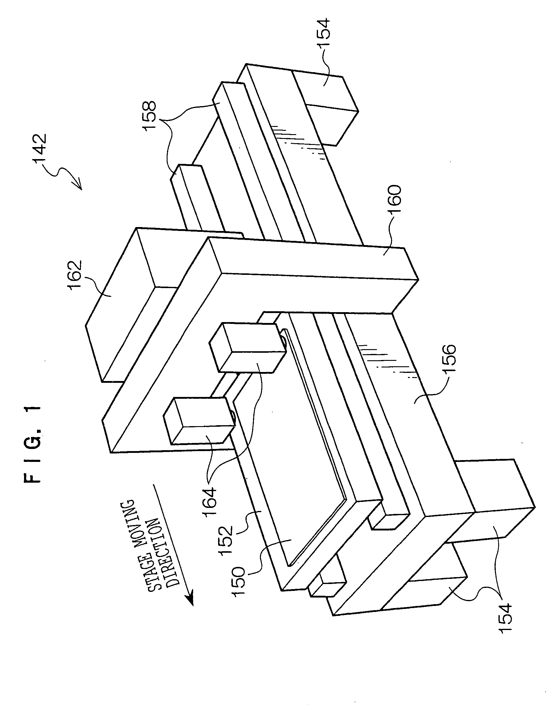
As shown in FIG. 1, an exposure device 142 to which an exposure head pertaining to the embodiment of the invention has been applied is disposed with a planar stage 152 that includes a surface to which a sheet-like photosensitive material 150 is carried and retained. Two guides 158 that extend along the stage moving direction are disposed on an upper surface of a thick planar mount 156 supported by leg portions 154. The stage 152 is supported by the guides 158 so as to be capable of reciprocal movement. It should be noted that an unillustrated drive device for driving the stage 152 along the guides 158 is disposed in the exposure device 142.

A substantially U-shaped gate 160 is disposed at a central portion of the mount 156 so as to straddle the movement path of the stage 152. End portions of the gate 160 are fixed to both side surfaces of the mount ...


PUM

PropertyMeasurementUnit
reflectivityaaaaaaaaaa
angleaaaaaaaaaa
core diameteraaaaaaaaaa

Abstract

In an exposure head of the invention, plural first micro-focusing elements are arranged in a first microlens array so as to correspond to plural micromirrors in a DMD. An aperture array that includes plural apertures arranged so as to respectively correspond to the plural first micro-focusing elements is disposed. The apertures allow only main portions of Fraunhofer diffraction images to be transmitted therethrough. The main portions of the Fraunhofer diffraction images transmitted through the apertures are imaged on an exposure plane by second micro-focusing elements of a second microlens array. According to the exposure head of the invention, cross-talk light and scattered light can be effectively reduced, and beam diameters of beam spots projected on the exposure plane through the apertures can be adjusted to a required size.

Description

CROSS-REFERENCE TO RELATED APPLICATION This application claims priority under 35 USC 119 from Japanese Patent Application No. 2003-204404, the disclosures of which are incorporated by reference herein. BACKGROUND OF THE INVENTION 1. Field of the Invention The present invention relates to an exposure head for exposing an exposure surface of a photosensitive material or the like with a bundle of light beams modulated by a spatial light modulator in correspondence to image data. 2. Description of the Related Art Conventionally, various exposure heads for conducting image exposure with light beams modulated in correspondence to image data using a spatial light modulator such as a digital micromirror device (DMD) have been proposed. As the DMD, a mirror device is used where numerous micromirrors, in which the angles of reflection surfaces thereof change in correspondence to control signals, are two-dimensionally arranged on a semiconductor substrate such as silicon. The exposure h...

Claims


Application Information

Patent Timeline
Patent Type & Authority Applications(United States)
IPC IPC(8): B41J2/465G03F7/20
CPCG03F7/70791B41J2/465G03F7/20
Inventor NOGUCHI, MASARUISHIKAWA, HIROMI
Owner ADTEC ENG
Why Eureka
Try Eureka